")
")
")
")
")
")
Removing and installing Mazda 3 connecting shaft
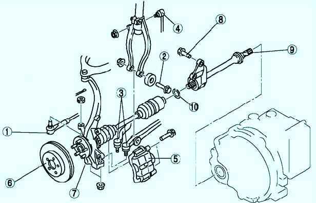
The components of the front drive shaft are shown in fig. 1
Preliminary check of intermediate shaft
Check that the connecting shaft is not twisted or cracked
Turn the connecting shaft by hand and check the smooth rotation of the bearing (fig. 2).
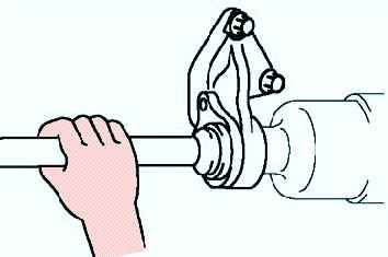
Replace the shaft if necessary.
Performing the following procedures without first removing the anti-lock braking system wheel speed sensor may result in an open circuit in the wiring harness if the harness is taut by mistake.
Before performing the following operations, remove the anti-lock braking system wheel speed sensor (body side) and mount it in a suitable location where the sensor will not be mistakenly damaged during maintenance.
Remove
Drain the gearbox oil.
Remove the anti-lock brake sensor.
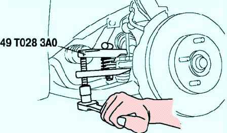
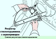
Using the special tool, remove the tie rod end ball joint (fig. 3).
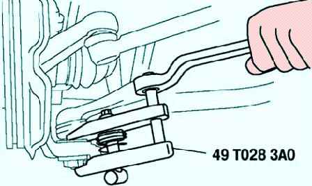
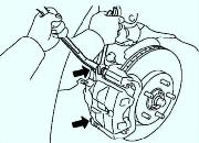
Using the special tool, remove the lower arm ball joint (fig. 4).
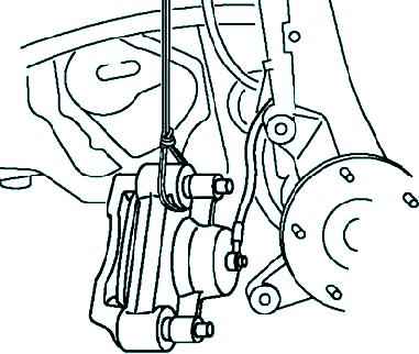
Remove the brake caliper and hang it on a wire (fig. 5).
Install the special tool to hold the side gear after removing the connecting shaft to the gearbox.
Remove and install other components in the reverse order of removal.
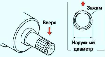
Before installing, put a new clamp on the connecting shaft with the slot facing upwards (fig. 7)
Sharp edges of the connecting shaft can cut or pierce the gland.
Be careful when separating the connecting shaft from the gearbox. Pull the connecting shaft straight out.
After installation, measure the outer diameter.
If it is too high, reinstall with a new clip. Maximum outer diameter: 31.2 mm.
Details
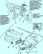
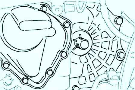
Remove the right front wheel drive assembly

Using a 17 mm socket wrench, unscrew the three bolts securing the intermediate support to the cylinder block

On vehicles with a 2.0 engine, the intermediate support is attached to the cylinder block bracket with two bolts

Carefully (trying not to damage the shaft splines, the gearbox oil seal) remove the shaft from the gearbox and remove it
The intermediate bearing (the most wear part of the intermediate shaft) can be replaced separately
Install parts in reverse order