")
")
")
")
")
")
Cylinder head disassembly
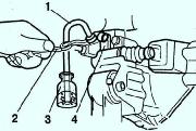
Remove the engine lifting eyes (fig. 1).
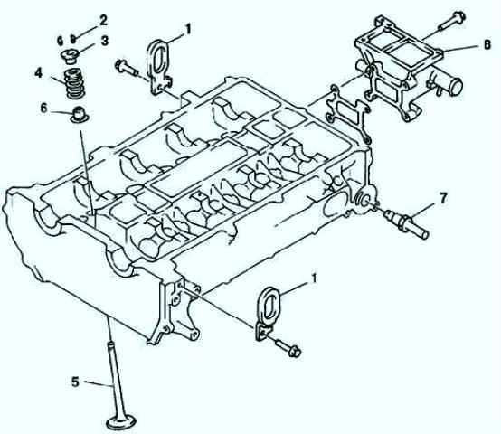
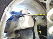
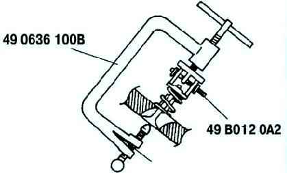
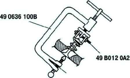
Remove the valve cotters using special tools (Fig. 2).
Remove the upper valve spring head. Remove the valve spring and valve.
Using a special tool, remove the oil seal (Fig. 3).
Remove the recirculation tube.
Remove the housing of the cooling system outlet pipes.
Detection
Checking the valve guide
Measure the thickness of each valve head (fig. 4).
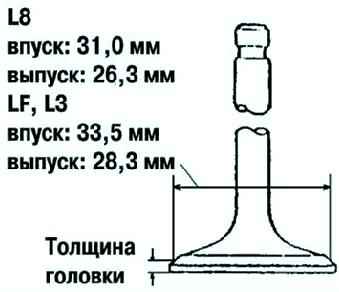
If the thickness is not correct, replace the valve.
Head Thickness: Inlet: 1.62mm. Issue: 1, 82 mm.
Measuring valve length
Measure the length of each valve (fig. 5). If the length is not correct, replace the valve.
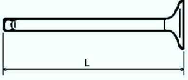
Standard length L: Inlet: 102.99 - 103.79 mm; Outlet: 104.25-105.05 mm.
Minimum length L: Inlet: 102.99 mm; Outlet: 103.79 mm.
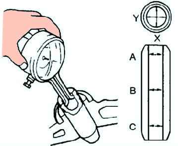
Measuring the valve stem diameter
Measure with a micrometer the stem diameter of each valve in the X and Y directions at three points (A, B, and C) as shown in Figure 6.

If the diameter is not correct, replace the valve.
Standard diameter: - Inlet: 5.470-5.485 mm; - Outlet: 5.465-5.480 mm.
Maximum diameter: - Inlet: 5.440 mm; - Outlet: 5.435 mm.
Measuring the inner diameter of the valve guide
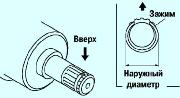
Measure the inside diameter of each valve guide in the X and Y directions at three points (A, B, and C) as shown in Figure 7.
If the diameter is not correct, replace the valve guide.
Standard bore: - Inlet: 5.509-5.539mm; - Outlet: 5.509-5.539 mm.
Calculate the clearance between the valve stem and valve guide by subtracting the outside diameter of the valve stem from the inside diameter of the corresponding valve guide (Figure 8).
If the result is not correct, replace the valve and/or valve guide.
Normal clearance:
- - Inlet: 0.024-0.069 mm;
- - Outlet: 0.029 - 0.074 mm.
- - Maximum gap: 0.10 mm.
Measuring the protrusion of the valve guide
Measure the protrusion height (dimension A) of each valve guide, excluding the lower valve spring seat (fig. 9).
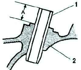
If the height is not correct, replace the valve guide.
Standard diameter:
- - Inlet: 12.2-12.8 mm;
- - Outlet: 12.2-12.8 mm.
Replacing the valve guide
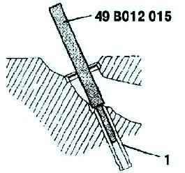
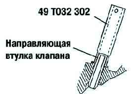
Remove the valve guide from the combustion chamber side using the special tool (fig. 10).
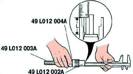
Assemble the special tools so that the depth L corresponds to that indicated (fig. 11). - Depth L: - Inlet: 12.2-12.8 mm; - Outlet: 12.2-12.8 mm
Pushing in the valve guide
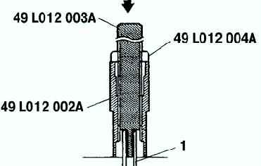
Press the valve guide from the side opposite the camshaft until the special tool stops against the cylinder head (Fig. 12).
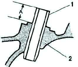
Check that the projection height of the valve guide (dimension A) is correct (see fig. 13).
Standard height: - Inlet: 12.2-12.8 mm; - Outlet: 12.2-12.8 mm
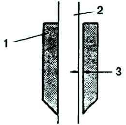
Checking and repairing the valve seat
Measure the width of the valve seat contact area.
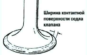
If necessary, finish the valve seat or disc using the appropriate tool (fig. 14). Standard width: 1.2-1.6 mm.
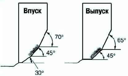
Check the alignment of the contact surface with the valve seat (fig. 15).
If the contact surface is outwardly displaced, machine the valve seat with a cutting tool with a working angle of 70° (inlet) or 65° (exhaust) and a cutting tool with an angle of 45°.
If the contact surface is displaced inwards, machine the valve seat with a cutting tool with a working angle of 30° (Inlet) or 0° (Exhaust) and a cutting tool with an angle of 45°.
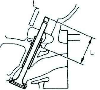
Check the valve seat depth. Measure the protrusion (dimension L) of the valve stem (fig. 16).
If the measured height is not correct, replace the cylinder head.
Standard size L:
- - Inlet: 40.64–42.24 mm;
- - Outlet: 40.50-42.10 mm.
Valve spring check
Apply a compressive force to the spring and check the height of the spring (fig. 17).
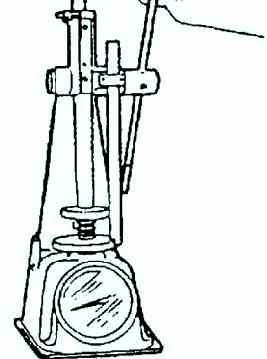
If the height is not correct, replace the valve spring.
Clamping force: 494.9 N. Standard height: 27.80 mm.
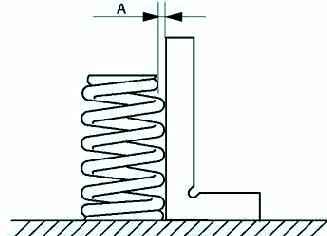
Measure the out-of-squareness of the valve spring using a square, as shown in Figure 19.
Rotate the valve spring 360° to measure the largest distance "A".
If the misalignment is not correct, replace the valve spring.
Maximum valve spring misalignment: 1% (2.10 mm).
Checking distribution shaft
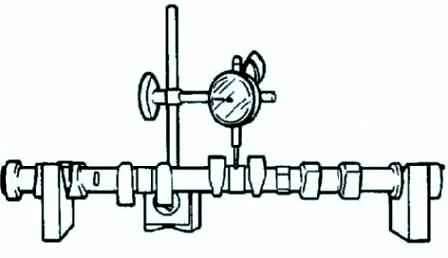
Mount journals #1 and #5 of the camshaft onto prisms.
Measure the camshaft runout (fig. 20). If the runout is not correct, replace the camshaft. Maximum runout: 0.03 mm.
Measure the height of the cam contour at two points as shown in Figure 21.
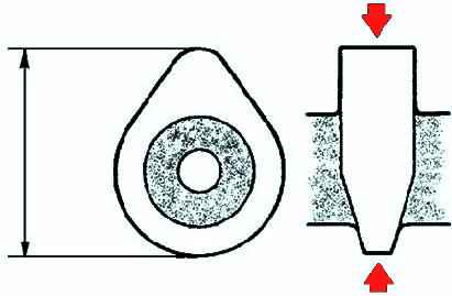
If the height is not correct, replace the camshaft.
Neck №1. Standard camshaft height L8:
- - Inlet - 40.79 mm;
- - Release - 41.08 mm.
- Camshaft LF, L3:
- - Inlet - 42.12 mm;
- - Release - 41.08 mm.
With variable valve timing:
- - Inlet - 42.44 mm;
- - Release - 41.18 mm.
- - Neck №5
Standard camshaft height L8:
- - Inlet - 40.692 mm;
- - Outlet - 40.982 mm.
LF, L3 camshaft:
- - Inlet - 42.022 mm;
- - Outlet - 40.982 mm.
With variable valve timing:
- - Inlet - 42.342 mm;
- - Outlet - 41.082 mm.
Measuring the diameter of the camshaft journal
Measure the diameters of the shaft journal in the X and Y directions at two points (A and B) as shown in Figure 22.
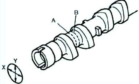
If the values are not correct, replace the camshaft.
Standard diameter: 24.96 - 24.98 mm.
Minimum diameter: 24.95 mm.
Measuring the radial clearance of the camshaft journal
Remove the valve lifter.
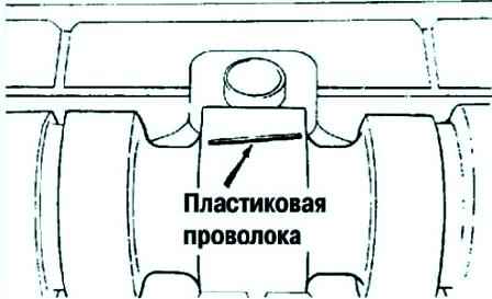
Place pieces of calibrated plastic wire on top of the camshaft journals, positioning them along the axis (Fig. 23).
Install the camshaft bearing cap.
Remove the camshaft bearing cap.
Measure the radial clearance. If the clearance is not correct, replace the cylinder head.
- Normal gap 0.04-0.08 mm
- Maximum gap: 0.09 mm
Measuring the axial clearance of the camshaft journal
Install the camshaft bearing cap.
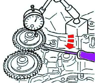
Measure the camshaft end play (Fig. 24).
If the clearance is not correct, replace the cylinder head or camshaft.
Standard axial clearance: 0.09 - 0.24 mm.
Maximum axial clearance: 0.25 mm.
Remove the camshaft bearing cap again.
Checking the valve tappet
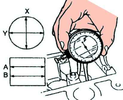
Measure the inner diameter of the tappet bore in the X and Y directions at two points (A and B) (fig. 25).
Inner diameter: 31.00 - 31.03 mm.
Measure the outer diameter of the tappet body in the X and Y directions at two points (A and B) (fig. 26).
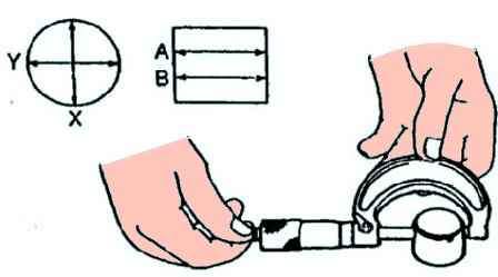
Outer diameter: 30.97-30.98 mm.
Subtract the outside diameter of the valve lifter body from the inside diameter of the valve lifter bore.
If the clearance is not correct, replace the valve lifter or cylinder head.
Standard gap: 0.02 - 0.06 mm. Maximum: 0.15 mm.
Cylinder head assembly
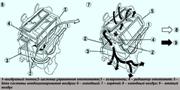
Install the cooling system outlet housing.
Install the recirculation tube.
Installing the oil seal
Press the valve stem seal onto the valve guide by hand.
Lightly press with a special tool using a nylon hammer (Fig. 27).
Install the valves, valve springs, and valve spring top caps.
Install the valve cotters using the special tools (fig. 28).
Install the engine lifting eyes.
Install a new cylinder head gasket.