")
")
")
")
")
")
Pre-operations
Disconnect the negative battery cable.
Remove the spark plugs.
Remove the right wheel.
Remove the right mudguard.
Loosen the coolant pump pulley bolt and remove the drive belt.
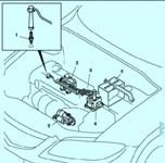
Remove the crankshaft position sensor.
Drain the engine oil.
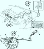
Disconnect the fuel lines by wrapping the connectors with a rag.
Remove the fuel pump drive belt.
Remove the fuel pump.
Remove the right joint shaft from the intermediate propeller shaft.
Remove the bottom plug of the engine front cover.
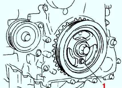
Removing the crankshaft pulley mounting bolt
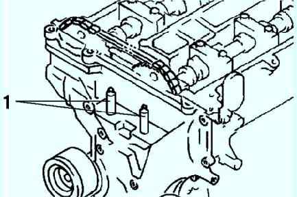
Remove the bottom plug of the cylinder block.
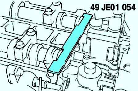
Install the special tool (fig. 1).
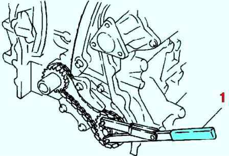
Turn the crankshaft clockwise to TDC on cylinder #1.
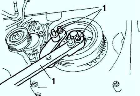
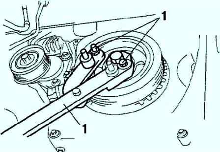
Hold the crankshaft with a special tool (fig. 2).
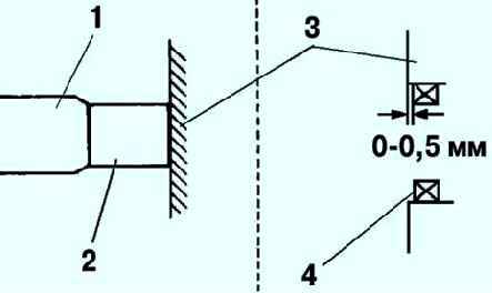
Removing the chain tensioner
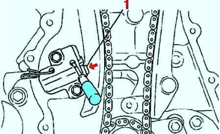
Using a thin screwdriver, pry the chain tensioner ratchet away from the ratchet shaft (fig. 3).
Slowly push down the tensioner piston. Hold the tensioner piston using 1.5mm thick wire or a paper clip.
Suspend the engine using the special tools.
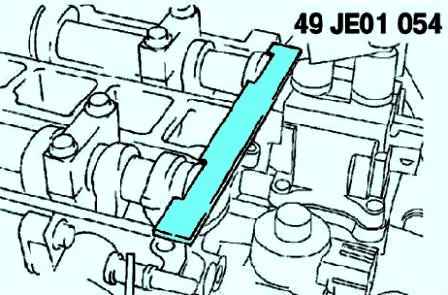
Removing the timing chain
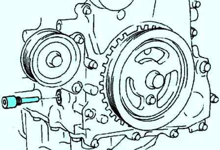
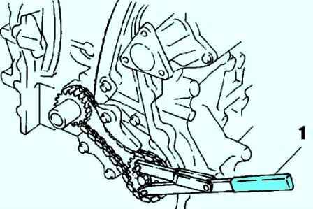
Fix the oil pump sprocket with the special tool (fig. 4).
After that, remove the sprocket and chain.
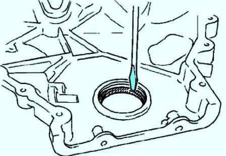
Using a screwdriver, remove the front oil seal (fig. 5).
Installing the timing chain
Install the oil pump sprocket and fix it with the special tool (see fig. 6).
Install the special tool on the camshaft (see fig. 7).
Install the timing chain.
Remove the retaining wire or paper clip from the auto tensioner to tension the timing chain.
Installing the engine front cover
Apply silicone sealant to the engine front cover at the locations shown in Figure 8.
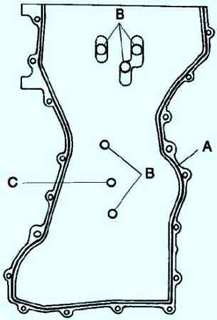
Install the cover 10 minutes after applying the sealant.
For model L3 engines, sealant is not required in area C (see fig. 8).
The thickness of the applied sealant: 2.0-3.0 mm for area A, 1.5-2.5 mm for area B.
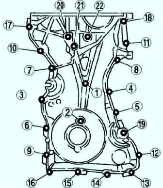
Install the cylinder head cover bolts in the order shown in Figure 9.
- Bolts 1-18 tightening torque 8.0-11.5 Nm
- Bolts 19-22 tightening torque 40-55 Nm
Installing the front crankshaft oil seal
Apply clean engine oil to the oil seal. Lightly press in the oil seal by hand.
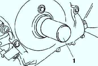
Press the oil seal using a special tool and a hammer (Fig. 10).
Installing No. 3 engine rubber mount and No. 3 engine mounting bracket
Tighten the threaded stud of the motor support bracket #3 with a tightening torque of 7-13 Nm (fig. 12).
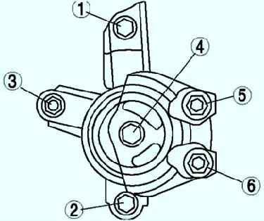
Tighten the #3 engine mount bracket bolt and nut in the order shown in Figure 13.
Installing the crankshaft pulley mounting bolt
Install the special tool on the camshaft (see fig. 14).
Install the M6x1.0 stop bolt and tighten it by hand (fig. 15).
Turn the crankshaft clockwise to TDC on cylinder #1.
Hold the crankshaft pulley with a special tool (see fig. 16).
Tighten the crankshaft pulley mounting bolt in two steps: tighten the bolt to 96–104 Nm; tighten the bolt 87–93°
Remove the M6x1.0 bolt. Remove the special tool from the camshaft.
Remove the special tool from the hole in the bottom plug of the cylinder block.
Turn the crankshaft clockwise two turns to TDC on cylinder #1.
If the TDC position cannot be reached, loosen the crankshaft pulley mounting bolt and repeat the above steps.
Install the bottom plug of the cylinder block and tighten it with a tightening torque of 18–22 Nm.
Installing the cylinder head cover
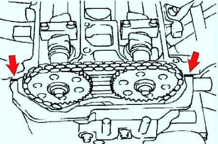
Apply silicone sealant to the mating surfaces of the cylinder block at the locations indicated by the arrows (fig. 17).
Diameter of application point – 4.0–6.0 mm.
Install the cylinder head cover with a new gasket.
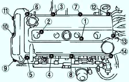
Tighten the fastening bolts in the order shown in Figure 18 with a tightening torque of 8–11.5 Nm.