")
")
")
")
")
")
A control pilot valve that directs fluid from the power steering pump to one side or the other of the steering rack piston
The piston and rack are one integral part of the steering mechanism
The gear rack piston converts fluid pressure into a linear force that moves the rack left or right.
This force is transmitted through the tie rods and tie rod ends to the steering knuckles that turn the front wheels.
If the hydraulic booster fails, the vehicle will be driven normally.
This requires more effort.
The rotational movement of the steering wheel is transmitted to the gear.
When the gear rotates, its teeth engage with the teeth of the rack, thereby causing the rack to move.
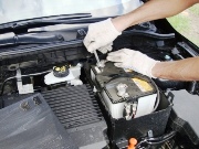
Remove
When removing the steering wheel, do not hit the shaft with a hammer. The steering column may be deformed.
Set the vehicle's wheels to straight ahead.
Remove the steering wheel with a suitable puller. Article on removing the steering wheel - Removing the steering wheel of a Mazda 3
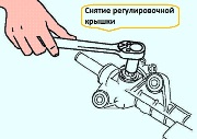
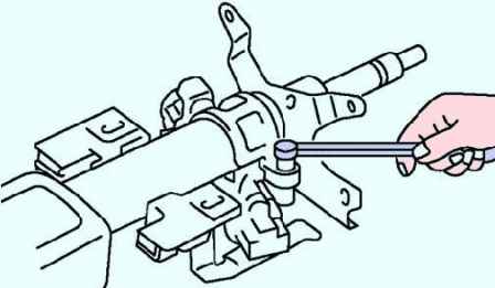
Using a chisel and a hammer, make grooves in the heads of the steering lock mounting bolts. Loosen the screws with a screwdriver.
Remove the part of the steering lock mechanism (fig. 2).
Check
Check the steering column bearing for damage.
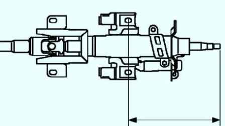
Check the length of the steering shaft (fig. 3).
Replace the steering shaft if necessary. Length: 211.6mm
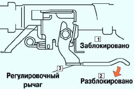
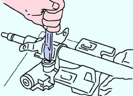
Check the operation of the steering column tilt and fore/aft adjustment mechanisms (Fig. 4).
Ensure that the lever moves smoothly from the unlocked to the locked position.
Make sure the steering shaft is secure when the lever is in the "locked" position.
Replace the steering shaft if necessary.
Installation
Install the steering lock part on the steering shaft.
Make sure the locking mechanism works properly.
Install new bolts securing the locking mechanism.
Tighten the bolts until the heads break off (fig. 5).
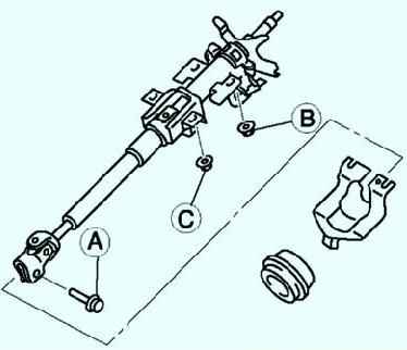
Lock the steering column tilt lever (fig. 6).
Tighten the bolt (A). Tighten nut (B). Tighten the nut (C)
Do not strike in the direction of the axis of the shaft.
Set the wheels of the car to the straight ahead position, install the steering wheel.