Removing and installing refrigerant lines (LF) Mazda 3
Disconnect the negative cable from the battery.
Discharge the coolant
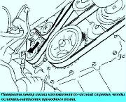
Remove the power steering reservoir.
Remove the expansion tank of the cooling system
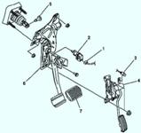
Remove the throttle cable.
Remove the power steering hose bracket.
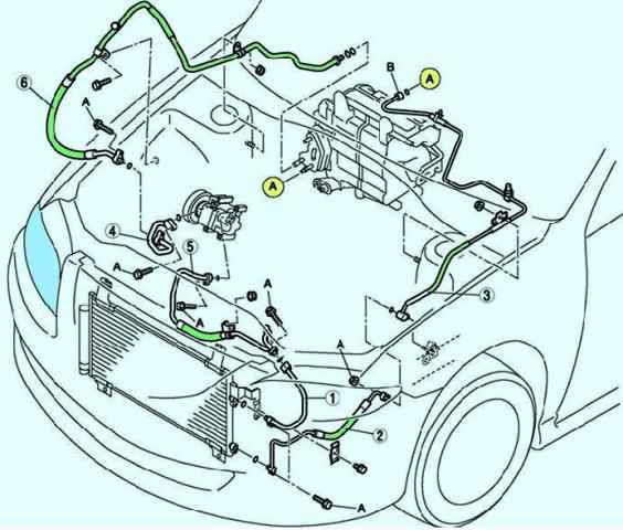
Remove in the order shown in the table. Avoid spilling oil from the compressor.
If moisture or impurities enter the cooling circuit, the cooling capacity of the circuit will be reduced, and abnormal noise will be heard.
Always plug open fittings after removing any parts of the refrigeration circuit to prevent moisture or impurities from entering the circuit.
Separation of the insulating joint
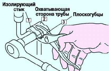
To separate pipes with an insulating joint, clamp the female side of the pipe with pliers or a similar tool, and then unscrew the connecting bolt or nut (Fig. 2)
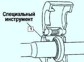
Install the special tool on the spring lock coupling (fig. 3).
Insert the protruding element of the special tool all the way into the holder, controlling the position of the protruding element through the viewing window.
Use the tool to detach the male pipe or hose from the female by pulling out the male pipe or hose.
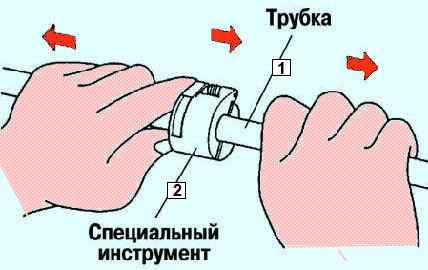
The male tube or hose can be easily detached from the female part by pulling it out while simultaneously pressing on the protruding element of the special tool (Fig. 4).
Installation
Apply compressor oil to the o-rings and connect the tubes.
Tighten the connections.
Tighten the insulating joint bolt by hand.
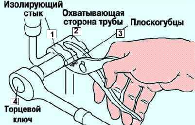
To connect tubing to an insulating joint, pinch the female side of the tubing with pliers or a similar tool, and then tighten the connecting bolt or nut with a torque wrench (fig. 5).
Attach the male tube or hose by screwing it into the female part until the spring on the male tube is past the flare of the female tube.
Perform performance tests on the refrigeration circuit.
When replacing a male tube or hose, the appearance of an indicator ring after connection indicates that the connection is blocked.
A/C Troubleshooting Index
Element - Description
Insufficient air supply through the vents - Faulty vents and/or ducts
The flow of air supplied through the openings does not change. (Automatic air conditioning system) - Fan failure
The flow of air supplied through the openings does not change. (Manual air conditioning system) - Fan failure
Air intake mode does not change - Air intake mode does not change when switching REC/FRESH mode (recirculation/fresh air)
Temperature control by the air conditioner control unit is not carried out - Malfunction in the air conditioning unit or the air mixing system of the air conditioner control unit
Windshield fogging up - The air conditioning compressor does not work, in the defroster mode or defroster heating mode
The air intake mode does not switch to FRESH (fresh) when the defrost mode is on or the defrost/heater mode is on
The air supplied through the openings is not cold enough - The magnetic clutch works, but the air conditioning system is faulty
Air not cooling - Magnetic clutch not working
Air conditioning noise - Noise from magnetic coupling, air conditioning compressor, refrigerant hose or line


