")
")
")
")
")
")
Removing and installing rear wheel hub Mazda 3
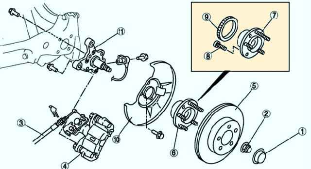
Rear wheel hub components are shown in fig. 1.
Checking the clearance in the rear wheel hub bearing
Remove the rear wheel
Disconnect the front disc brake caliper.
Remove the brake disc (fig. 2)

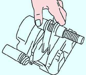
Mount the dial indicator against the wheel hub (fig. 3).
While moving the wheel hub manually in the axial direction, measure the clearance in the hub bearing.
Maximum: 0.05 mm. If the clearance exceeds the maximum, replace the bearing.
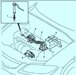
Performing the following procedures without first removing the ABS wheel speed sensor may result in an open circuit in the wiring harness if the harness is taut by mistake.
Before performing the following steps, remove the ABS wheel speed sensor (body side) and mount it in a suitable location where the sensor will not be mistakenly damaged during maintenance.
Removing and installing the rear wheel hub
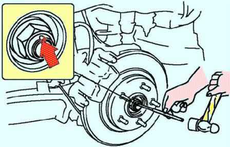
Knock out the bent part of the locknut with a small chisel and hammer (fig. 4).
Lock the hub by applying the brake. Loosen the locknut.
The anti-lock brake sensor rotor can only be removed if it is replaced.
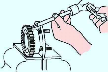
Using a chisel, remove the ABS sensor rotor (fig. 5).
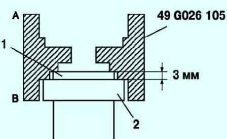
In order to install the ABS sensor rotor, orient the special tool so that the marking B is facing down (Fig. 6)
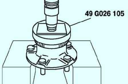
Press the new sensor rotor using the special tool and a press (fig. 7)
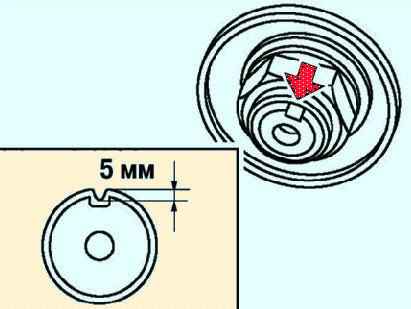
Install the new locknut and lock it as shown in Figure 8