Mazda 3 manual transmission assembly
Installation of individual components of the differential, as well as verification procedures, are given below
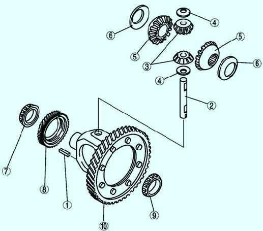
Assemble in the order shown in Figure 1.
Installing gear bearings
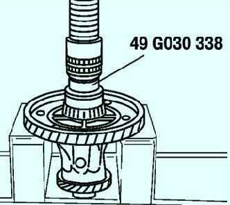
Using the special tool, install the new bearing (ring end) (fig. 2). Install the speedometer drive gear.
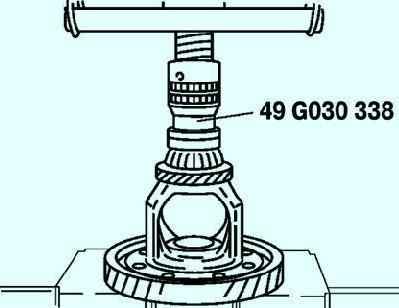
Using a special tool, install a new bearing (on the side opposite the ring gear) (fig. 3)
Roll pin assembly
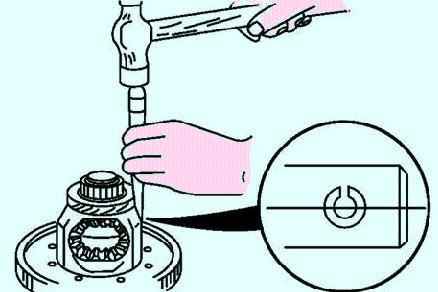
Install a new roll pin as shown in Figure 4 to hold the planetary axle.
Measure the clearance according to the following procedure. Install the left and right drive shafts into the differential.
Support the drive shafts with prisms.
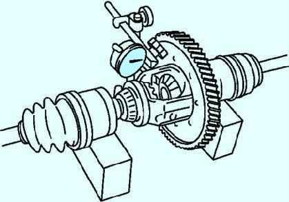
Measure the clearance of both satellites (fig. 5). Gap: 0.050-0.150 mm.
If the measurement results are abnormal, replace worn and damaged parts
Adjusting the bearing preload
Install the input and output shaft bearing races into the final drive housing (gaskets removed).
Install the clutch housing on the gearbox lug in the final drive unit, install the differential bearing race in the clutch housing.
Place a piece of pipe on the bearing race and press it all the way into the clutch housing.
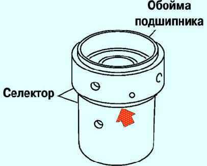
Install the bearing races in the special tools (selector) as shown in the figure fig. 6.
Turn the selector until the gap is eliminated, indicated by the arrow in Figure 6.
Installing the differential in the clutch housing
Install the differential in the clutch housing, install the bearing race and the special tool (selector) on the differential.
Install special tools (selectors) for the input and output shafts in the clutch housing.
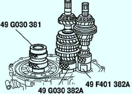
Install the shafts with gears as shown in Figure 7.
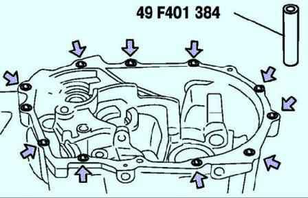
Install the special tool (sleeves) in the positions shown in figure 8
Installing the final drive housing
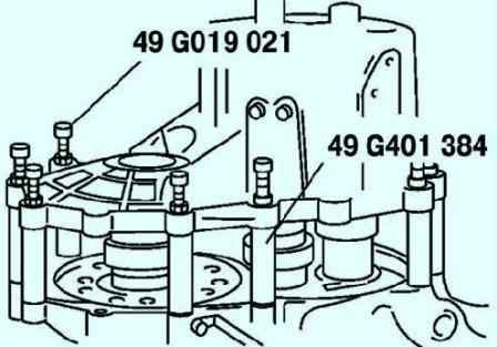
Install the final drive housing and tighten the special tool (bolts) with the rated tightening torque (fig. 9).
Tightening torque: 37.3 - 52.0 Nm.
Elimination of gaps of the primary, secondary shafts and differential of the final drive housing
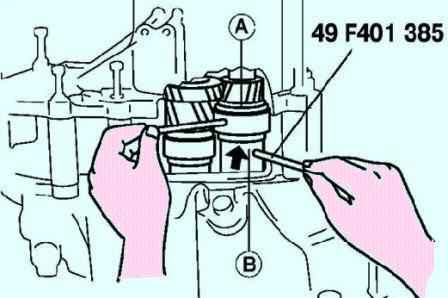
In order to install the bearings, install the special tools (rods) in the holes A and B of the selectors and turn the selectors in such a way as to increase the clearance.
After that, turn the special tool in the opposite direction until the gaps are eliminated (Fig. 10).

Manually expand the selectors as far as they will go (Figure 11).
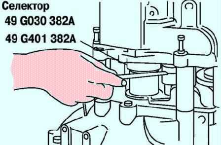
Use a feeler gauge to measure the gap in the special tool (selector) (fig. 12).
Measure the gap around the entire circumference of the selector. Remember the maximum value and select the spacer as follows.
Input Shaft Shim: Select the thinnest allowable shim from the table to obtain standard clearance.
Standard clearance: 0-0.05 mm.
Example: stylus measurement value is 0.57 mm;
- spacer thickness range: (0.57mm - 0.05mm) - (0.57mm - 0mm)= 0.52mm - 0.57mm;
- spacer: 0.55 mm.
Mainshaft shim: Select the thinnest acceptable mainshaft shim from the table to obtain standard clearance.
Preload: 0.03–0.08 mm.
Example: stylus measurement value: 0.57 mm; gasket thickness range: (0.57 mm + 0.03 mm) - (0.57 mm + + 0.08 mm) = 0.60 mm - 0.65 mm; spacer: 0.60 mm.
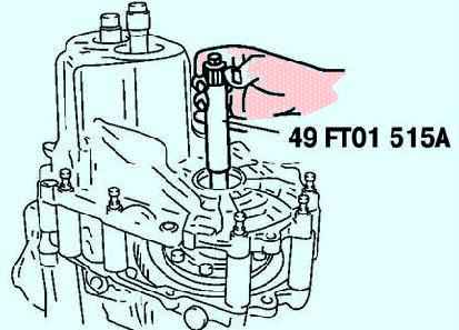
Install the special tool and dynamometer or torque wrench (fig. 13).
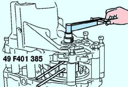
Adjust the gap of the special tool (selector) to get the correct preload/dynamometer value (fig. 14).
Read the preload value when the differential starts to turn.
Measure several times and calculate the average.
Preload: 0.5 Nm. Value on the dynamometer: 5 N.
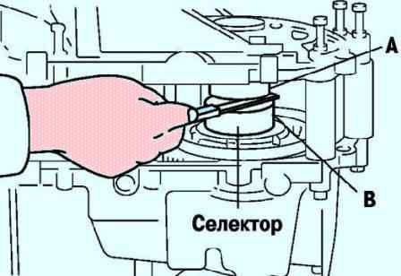
Use a feeler gauge to measure the gap in the differential selector (fig. 15).
Add 0.15mm to the measured gap and select the shim combination that gives the closest fit to the measured value.
Example: 0.32mm + 0.15mm = 0.47mm. Closest padding (thick side): 0.47mm - 0.50mm
Remove the final drive housing and special tool.
Remove the selectors, input shaft and differential.
Remove the bearing races.
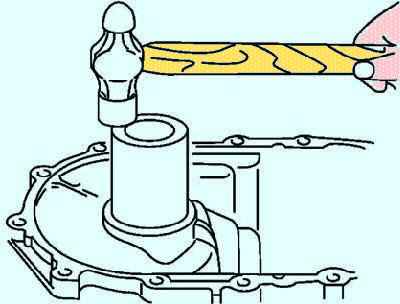
Install the shim(s) and input shaft bearing race using a suitable pipe (fig. 16).
Use the shim(s) selected when adjusting the bearing preload.
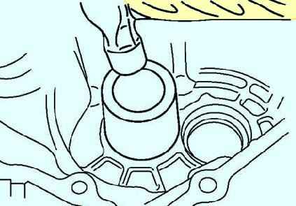
Install the shim(s) and differential shaft bearing race using a suitable tube (fig. 17).
Use the adjuster pad(s) selected when adjusting the bearing preload.
Measuring the load of the primary, secondary shafts and the differential shaft of the final drive housing
Install the input shaft with gears and differential into the clutch housing.
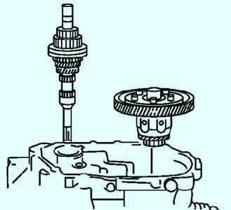
Install the final drive housing and tighten the input shaft fasteners to the specified torque (Fig. 18). Tightening torque: 37.3 - 52.0 Nm.
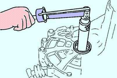
Install the special tool and dynamometer or torque wrench (fig. 19).
Make sure the preload is within specification.
If this is not the case, repeat the operations, starting with adjusting the preload in the bearings.
Preload: 1.4 - 1.9 Nm. Dynamometer reading: 14–19 N. Remove the special tool.
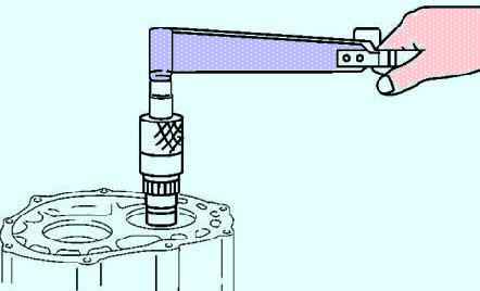
Install the gearbox in the final drive as shown in figure 20, install the special tool on the input shaft.
Make sure the preload is within specification.
If this is not the case, repeat the operations, starting with adjusting the preload in the bearings. Preload: 0.12 - 0.39 Nm.
Dynamometer reading: 1.2–3.9 N.
Remove the special tool, final drive housing, input shaft and differential.
Install the output shaft and final drive housing, tighten the fasteners to the rated torque. Tightening torque: 37.3 - 52.0 Nm.
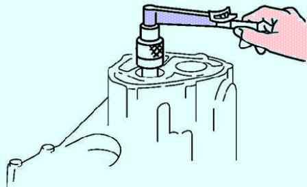
Install the special tool and dynamometer or torque wrench (fig. 21).
Make sure the preload is within specification.
If this is not the case, repeat the operations starting with adjusting the preload in the bearings.
Preload: 0.2 - 0.3 Nm. Dynamometer reading: 2–3 N.
Remove the special tool and the final drive housing.


