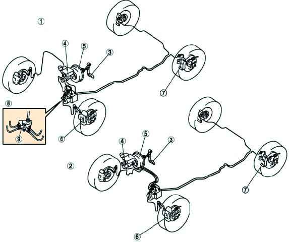
The vehicles are equipped with a hydraulic brake system.
Front disc brakes, rear disc or drum brakes
All brakes are equipped with automatic brake pad clearance adjustment.
Wear of the front disc brake pads is automatically compensated, the rear disc brake has a pad clearance adjustment mechanism.
The hydraulic system consists of two separate circuits.
The main brake cylinder includes separate reservoirs for two circuits, in case of fluid leakage or damage in one of the hydraulic actuators, the other remains active.
A dual pressure regulator distributes hydraulic pressure between the front and rear brakes to prevent rear wheel lockup.
The brake fluid level warning is given by a warning light activated by a sensor in the master cylinder reservoir.

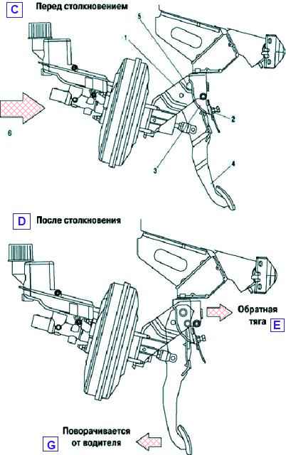
Crash-safe brake pedal
The safety brake pedal design minimizes pedal backlash.
This provides cushioning for the force of an impact on the rider's lower body.
In a frontal impact, movement of the engine and other components into the body causes the brake pedal bracket (A) to move backwards and separate from the brake pedal bracket (B).
Reverse movement of the brake pedal lever connected to the bracket support (A) is prevented by the stopper on the brake pedal bracket (B).
Consequently, the backward movement of the brake pedal lever is suppressed by the movement of the brake pedal bracket (A).

Vacuum brake booster reduces the force on the brake pedal, making driving easier.
The vacuum amplifier uses a diaphragm, on both sides of which a vacuum is created during normal operation.
During braking, air is supplied from one side of the diaphragm, forming atmospheric pressure.
Due to the pressure difference transmitted through the diaphragm, the pusher moves towards rarefaction (vacuum), providing an auxiliary force for braking.
When the brake pedal is released, air is pumped out of the amplifier cavity through the control valve, creating a vacuum.
The brake master cylinder is used on dual-circuit brake systems.
The front right and rear left brakes are actuated by the primary piston, while the front left and rear right brakes are actuated by the secondary piston.
The brake master cylinder combines the functions of a standard dual brake master cylinder plus a low brake fluid indicator and brake pressure regulator.
The pressure regulator limits the output pressure to the rear brakes after the pressure reaches the limit value in the master brake cylinder.
The regulator is used when less force is needed on the rear brakes to achieve optimal braking.
The brake fluid level sensor, located in the brake fluid reservoir, turns on the BRAKE warning light when it detects a low fluid level.
As soon as the level returns to normal, the BRAKE lamp goes out.
Anti-Lock Braking System (ABS)
Braking is most effective when the grip of the tire on the road surface is maximum.
During braking, the tire slides over the surface, and the circumferential speed of the wheel becomes less than the speed of the car.
The anti-lock braking system limits the pressure generated in the hydraulic brake actuator so that the amount of slip is optimal.
The operation of this system should be separate for each wheel.
The system should immediately respond to every change surface (traction coefficient) and vehicle load.
The anti-lock braking system prevents the wheels from locking during heavy braking, thereby reducing the braking distance.
The grip force between the wheels and the road in this case is greater if the wheels continue to rotate during braking.
Even with full braking, the car remains steerable.
Rate sensors, one for each wheel, measure wheel speed.
Based on the signals from the sensors, the electronic control unit calculates an average speed approximately corresponding to the speed of the vehicle.
By comparing the speed of rotation of each individual wheel with the average calculated speed, the electronic unit determines the slip state of the individual wheel and thereby determines which wheel is in the pre-lock state.
When one of the four wheel speed sensors transmits a locked wheel signal to the respective wheel, the ECU immediately sends a close signal to the respective inlet solenoid valve, which shuts off the brake fluid supply through the line to the wheel brake.
In this case, the braking force remains constant.
If the sliding continues, the release valve opens and the pressure in the hydraulic system of this brake decreases.
The wheel does not brake, excess brake fluid returns to the reservoir. As soon as the wheel starts spinning again, the intake valve opens and the exhaust valve closes.
The pressure in the circuit increases and the wheel brakes again.
The cycles of braking and free rotation of the wheel change very quickly (several times per second) and continue until the car stops or the brake pedal is released.
The process is repeated under hard braking separately for each wheel until the brake pedal is released.
The alarm system ensures that the ABS is turned off in case of any malfunction or low voltage in the vehicle's on-board network (below 10 V).
An ABS malfunction does not affect the operation of the brakes.
The hydraulic drive consists of a hydraulic unit, brake calipers and brake pipes.
The hydraulic unit includes an electric pressure pump and solenoid valves.
Dynamic stability control
The hydraulic control mechanism of the DSC HU/CM system and the control strategy of the system are essentially adopted from the previous model 323, except for the following:
- - DSC unit and hydraulic unit are combined for better serviceability;
- – lateral g-sensor and yaw rate sensor combined to improve maintainability;
- – brake fluid pressure sensor integrated in DSC HU/CM;
- – DSC HU/CM I/O pins changed;
- – Electric Brake Assist is used to improve safety;
- – DSC system switch is used to disable DSC operation;
- - The DSC HU/CM system outputs the speed signal to the audio unit, wiper/washer switch, car navigation unit, cruise control actuator and wire leveling control unit, and outputs the speed signal via CAN;
- – CAN communication system is used.
The DSC warning lamp is installed in the instrument cluster and notifies the driver of DSC activation (vehicle in side slip) or TCS activation (drive wheel slip) when the DSC system is not deactivated by the DSC system switch.
When the DSC system and CAN are OK, the DSC system warning lamp lights up for 2-4 seconds when the ignition key is turned to the ON position and turns off when the lamp function is checked.
When the system is malfunctioning, the DSC warning light stays on.
DSC system switch, DSC deactivation indicator lamp
The DSC system switch is installed on the instrument panel and turns off the DSC when the corresponding button is pressed.
The DSC Disable indicator lamp is located in the instrument cluster and notifies the driver that the DSC system is disabled when the switch is pressed. When the DSC system and CAN are OK, the DSC system warning lamp lights up for 2-4 seconds.
When the system is malfunctioning, the DSC warning light stays on.
Specifications of brake system components
Working brake system
Brake pedal:
Pedal height (reference value), mm - 136.4
Pedal clearance, mm - 4.0-8.4
Distance from the pedal to the floor (with an effort on the pedals of 147 N), mm - 89.8 or more
Brake booster:
Liquid pressure at pedal force 200 N, kPa
- at 0 kPa (0 mm Hg) - 500 or more
- at 66.7 kPa (500 mm Hg) - 6500 or more
Front brake (disc):
- Minimum brake pad thickness, mm - 2.0
- Minimum brake disc thickness, mm - 23
- Brake disc runout limit, mm - 0.05
Rear brake (disc):
- Minimum brake pad thickness, mm - 2.0
- Minimum brake disc thickness, mm - 9
- Brake disc runout limit, mm - 0.05
Brake fluid:
Type - SAE J1703, FMVSS116, DOT-3 or DOT-4
Parking brake system:
Lever travel at a force of 98 N applied at a point located at a distance of 50 mm from the end of the parking brake lever - 3-6


