")
")
")
")
")
")
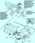
Mazda 3 manual transmission disassembly
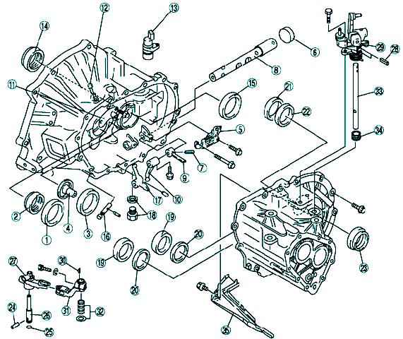
Disassemble in the order shown in Figure 1.
Procedures for removing individual crankcase components are shown below
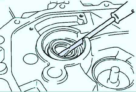
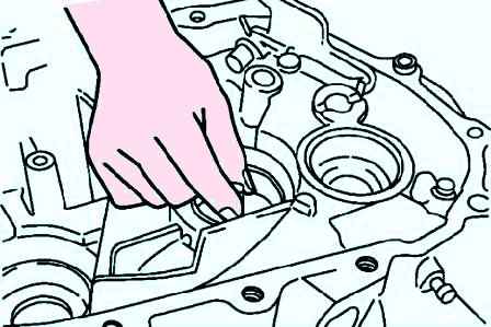
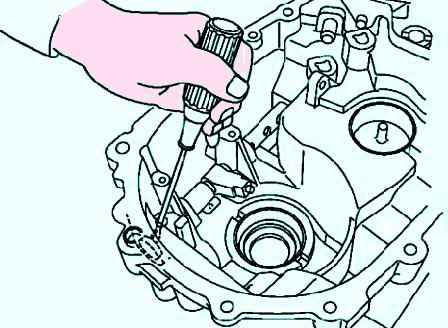
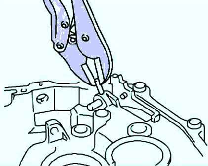
Remove the input shaft seal using a screwdriver (fig. 1).
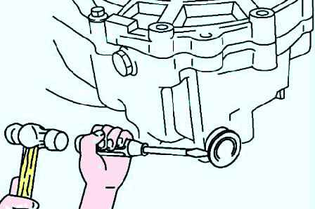
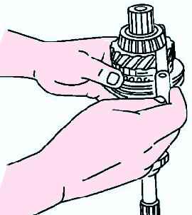
Remove the mainshaft bearing race and bell together (fig. 2).
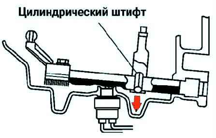
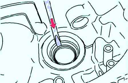
To disassemble the roll pin, align the clutch housing pin removal slot with the roll pin position.
Knock out the pin using a beard with a thin sting (fig. 3).
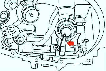
To remove the control stem, move it in the direction of the arrow shown in Figure 4.
Using a flat-blade screwdriver and a hammer, make a hole in the cover (fig. 5).
Remove the sealing cap by inserting a flathead screwdriver into the hole on the inside of the crankcase (fig. 6).
Remove the control stem seal using a screwdriver (fig. 7).
Remove the differential seal using a screwdriver (fig. 8).
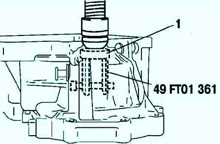
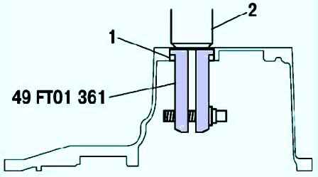
Before disassembling the differential bearing race, remove the outer race of the bearing using a special tool (fig. 9).
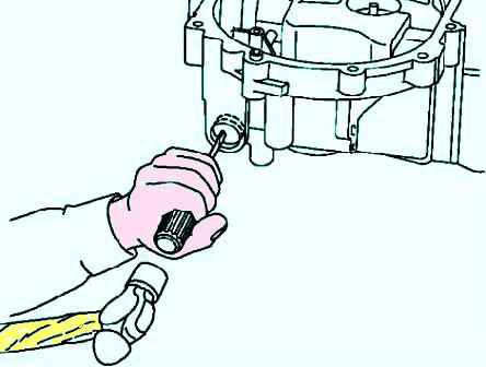
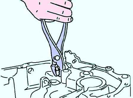
To remove the reverse lever shaft, first use pliers to remove the roll pin (fig. 10).
Protect the reverse lever shaft with a rag and use the same pliers to remove the shaft (fig. 11)
Using a special tool, remove the main gear housing bearing race (Fig. 12)
Checking input shaft elements
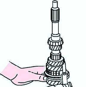
Measure the gap between the 3rd and 2nd gears (fig. 13).
If the gap exceeds the maximum, check the contact surfaces of the 2nd and 3rd gears, the 3rd/4th gear synchronizer clutch.
Replace worn or damaged parts. Gap: 0.05–0.20 mm. Maximum: 0.25 mm.
Measure the clearance between the 4th gear and the bearing (fig. 14).
If the clearance is greater than the maximum, check the contact surfaces of the 4th gear, bearing and 3/4th synchromesh clutch.
Replace worn or damaged parts. Gap: 0.17–0.37 mm. Maximum: 0.42 mm.