")
")
")
")
")
")
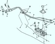
Rack and pinion steering with hydraulic booster
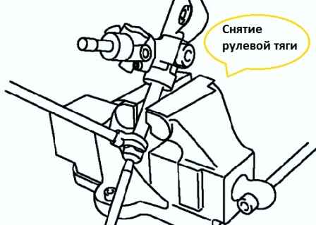
When fixing the steering bracket in a vise, place copper plates on the jaws of the vise, put a rag or similar material under it
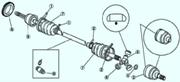
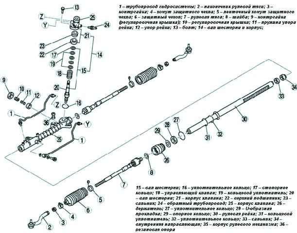
The steering gear and tie rod components are shown in fig. 1.
Tie rod disassembly
Remove the parts in the order shown in Figure 1.
Spread the puck.
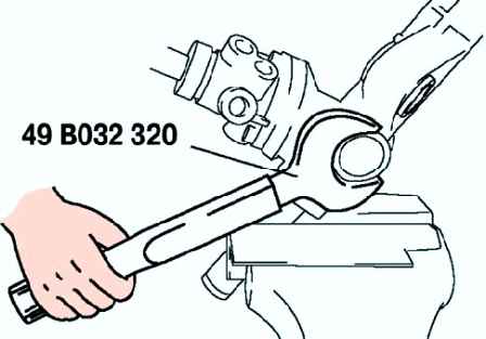
Remove the tie rod (fig. 2)
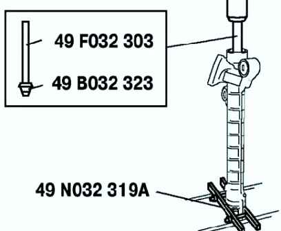
Remove the locknut using the special tool (fig. 3)
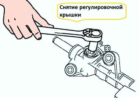
Remove the adjustment cap (fig. 4).
Disassembly of the gear shaft and housing
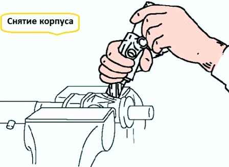
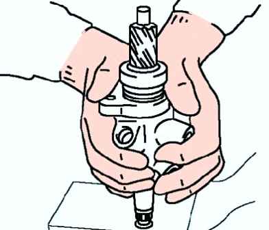
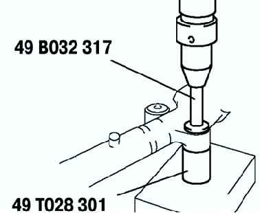
Holding the pinion shaft as shown in Figure 5, remove the housing and pinion shaft.
NOTE: If the pinion shaft cannot be removed by hand, use a press.
Push the gear shaft out of the valve body as shown in Figure 6
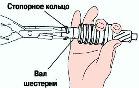
Carefully remove the retaining ring, being careful not to damage the gear shaft
Disassembly of the upper bearing and oil seal
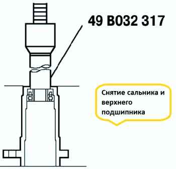
Install the special tool as shown in Figure 8.
Using a press, remove the stuffing box and upper bearing without applying pressure to the edge of the valve body
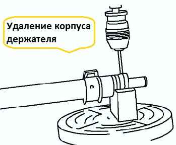
Cut off the deformed area with a drill (Fig. 9)
Carefully remove the holder, being careful not to damage the U-grommet.
Disassemble the holder.
Disassembly of the inner guide oil seal
Install the special tools on the side of the valve.
Install the special tool on the gear housing.
Press out the oil seal and inner guide (fig. 10).
Press the rubber support out of the steering gear housing using special tools and a press (fig. 11)