
")
")
")
")
")
")
The front suspension ( fig. 1 ) is equipped with McPherson struts.
The top end of each strut/spring assembly is attached to a custom car body panel
The lower end of the strut assembly is attached to the upper end of the steering knuckle (its swing arm).
The steering knuckle is connected by a ball joint to the outer end of the lower control arm.
All models are equipped with an anti-roll bar.
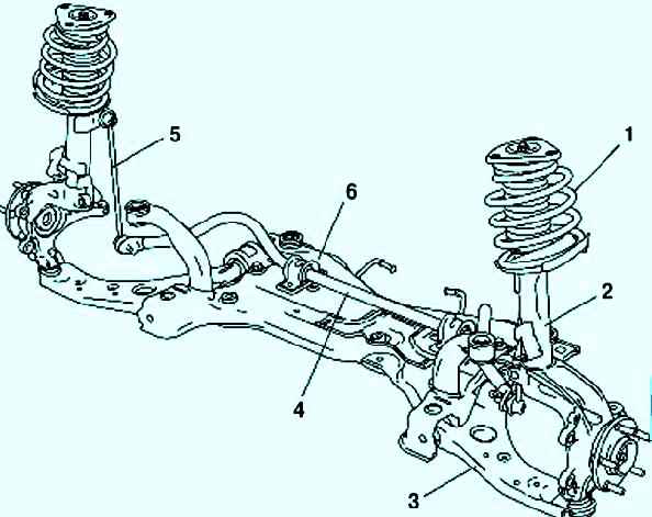
Independent suspension, with telescopic shock absorber struts, wishbones and torsion-type anti-roll bar
Upper suspension strut consists of shock absorber strut, coil spring, upper spring cup and upper strut mount
Outside, stabilizer strut and brake hose mounting brackets are welded to the strut body
The spring with its lower coil rests on the lower support cup, mounted on the suspension strut rod
Also, the upper support of the strut is installed on the suspension strut rod, consisting of a housing, a rubber cushion and a bearing
The bearing allows the strut, together with the spring and the upper spring support cup, to rotate when the steering wheel is turned, and the rubber cushion prevents the transmission of vibrations to the car body
The upper support of the front suspension strut is attached to the car body with three bolts.
To protect the shock absorber rod from dirt and dust, a protective cover is installed on it
To protect the car body from sharp impacts during suspension breakdown, a compression stroke buffer is installed on the shock absorber rod
From below, the front suspension strut is inserted into the steering knuckle and clamped with a coupling bolt, and the steering knuckle, in turn, is attached to the front suspension arm through a ball joint
A double-row ball bearing is pressed into the hole of the steering knuckle and fixed with a retaining ring.
Wheel hub pressed into bearing inner race
The ends of the anti-roll bar are connected to the front suspension struts of the car using stabilizer struts
The stabilizer bar is secured through rubber pads on the front subframe
Checking the technical condition of the front suspension
You can assess the technical condition of the suspension while the car is moving
When driving at low speed on uneven roads, the suspension should work without knocks, squeaks and other extraneous sounds
After crossing an obstacle, the vehicle must not sway
Performing check:
- Preparing the car
- Swing the front of the car vigorously in the vertical direction
If, due to inertia, the body continues to oscillate (more than two up and down movements) after it has stopped swinging, then one or both shock absorbers are faulty
To identify a faulty suspension strut, we repeat the test, applying force first on one side of the car, and then on the other
- Checking the condition of the hub bearing
- We inspect the shock absorber struts - fluid leakage from them is not allowed
- Checking the correct installation of the springs: the ends of the coils should rest against the special protrusions of the support cups
- Checking the integrity of the coils of the spring

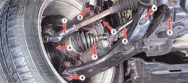
- Swinging the front lug of the lever with a mounting blade, we check the condition of the front silent block of the lever
There should be no backlash, otherwise the lever must be replaced

- Swinging the back of the lever with the mounting blade, we check the condition of the rear silent block of the lever
There should be no backlash, otherwise the lever must be replaced

- Using the mounting blade as a lever, we check the absence of backlash in the ball joint
If there is play, replace the lever
- Visually check the condition of the pillows and struts of the anti-roll bar and ball bearing covers.
Hinges and cushions with one-sided bulging of rubber, tears and cracks are replaceable
Also check the front suspension on the other side of the car
Check the tightness of the bolts and nuts securing the suspension parts, tighten them if necessary
Inspecting suspension parts. Deformation and fatigue cracks in suspension parts are not allowed. Damaged parts are replaced.
Tightening torques for threaded connections, Nm
- - wheel nuts 88-117;
- - front wheel bearing nut 32-39, tighten by 90 º;
- - nut of the coupling bolt for fastening the ball joint to the steering knuckle 43-59;
- - nut of the tie rod end pin 37-51;
- - nut of the coupling bolt for fastening the steering knuckle to the front suspension strut 54-74;
- - nut for fastening the front suspension strut to the car body 19-28;
- - nut of the front suspension strut rod 57-76;
- - bolt of the front fastening of the front suspension arm to the subframe 130-150;
- - bolts of the rear attachment of the front suspension arm to the subframe 98-132;
- - anti-roll bar 40-55 nuts;
- - bolts for fastening the brackets of the anti-roll bar of the front suspension to the subframe 40-55;
- - bolts for attaching the subframe to the body 182-247;
- - bolt of the front support of the power unit 93-117;
- - bolts for fastening the front brake caliper to the steering knuckle 102-118


