")
")
")
")
")
")
Removing and installing the vacuum booster for Mazda 3
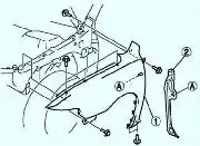
Remove the battery and battery tray
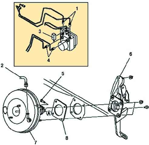
- - Remove the master cylinder.
- - Disconnect the brake line.
- - Disconnect the vacuum hoses.
- - Remove the brake pedal bolt and nuts.
- - Move the brake booster to the rear of the car.
- - Remove the brake pedal assembly.
Installing a vacuum booster
Installation is performed in the reverse order of removal.
After installation, check the brake pedal.
Checking the vacuum brake booster
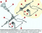
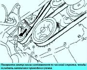
The operation of the vacuum brake booster located on the engine shield is based on the use of intake manifold vacuum and atmospheric air pressure.
After completing each operation, which included the removal of any of the elements of the brake system, make a test drive to check the operation of the vehicle's brakes.
Check your brakes while driving on a clean, dry and level road. Other test conditions may lead to inaccurate results.
Test your brakes at various speeds, both low and high brake loads.
The car should stop evenly, without pulling to the side.
Avoid locking up the brakes as this will damage tires and reduce braking efficiency and control.
Brake performance is also affected by tire condition, vehicle loading and front wheel alignment.
Checking the operation of the vacuum booster
Release the existing vacuum with the engine off by depressing the brake pedal several times at 5-second intervals.
Fully depressing the brake pedal, start the engine.
Make sure the gap between the brake pedal and the floor panel decreases as the vacuum in the engine stabilizes.
Leak test
Start the engine and let it idle for about 1 minute.
Shut it down by applying vacuum to the booster. Press the brake pedal several times with normal force and release the existing vacuum.
Ensure that as you press the brake pedal, the gap between the brake pedal and the floor panel gradually increases.
Start the engine.
Depress and hold the brake pedal, then stop the engine.
Keep the pedal depressed for about 30 seconds or more and check that the pedal travel does not change.
Checking and adjusting the protruding stem length
Using a manual vacuum pump, create a vacuum of 66.7 kPa (-500 mmHg) in the brake booster.
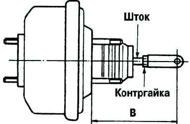
Loosen the lock nut and adjust the length of the pressure rod so that the length "B" becomes equal to the specified value (fig. 2).
Adjust until clearance between stem protrusion and screw is 0 mm - nominal length at 66.7 kPa (-500 mmHg) on vacuum gauge.