")
")
")
")
")
")
Remove the battery.
Remove the battery tray.
Remove the heatsink.
Drain the oil
Remove the power steering oil pump with oil filter without disconnecting the hose and place it so that it does not interfere.
Remove the air conditioning compressor without disconnecting the pipes.
Place the air conditioning compressor out of the way. Use a wire or rope to fix the compressor.
Remove the combined shaft from the intermediate drive shaft.
Remove the air filter, intake duct, accelerator cable with bracket and vacuum hose.
Remove the automatic transmission filter and selector cable. (models with automatic transmission).
Remove the vacuum hose and heater hose.
Remove the clutch slave cylinder and control cable (manual transmission models).
Remove the plastic fuel hose.
Disconnect the wiring harness in the engine compartment.
Remove the front tube.
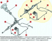
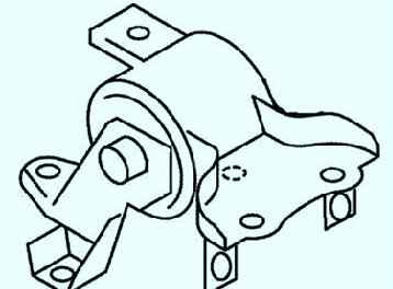
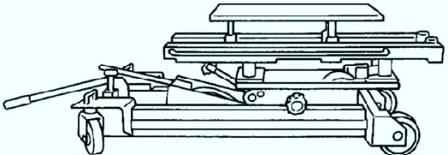
Remove the power unit (fig. 1).
Remove support #1
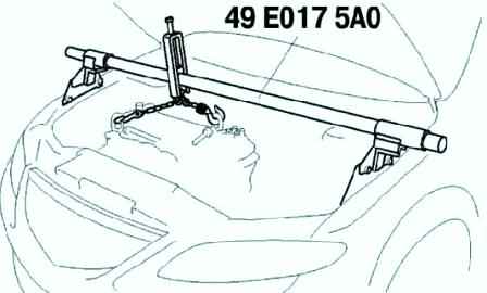
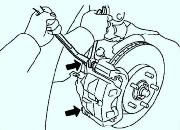
Suspend the engine using a special tool (Fig. 2.).
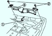
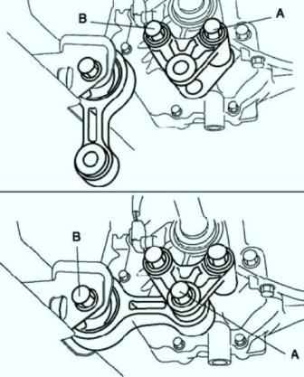
Remove the pinch bolt A from the #1 engine mount bracket side.
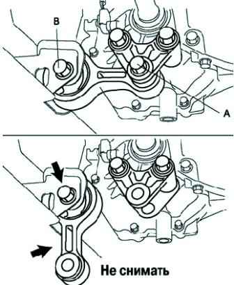
Loosen the tie bolt B on the body side until approximately three threads are visible (fig. 3)
Do not remove engine mount #1 from the vehicle (fig. 3).
Remove No. 4 engine mount bracket and No. 4 engine mount
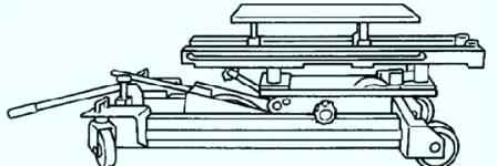
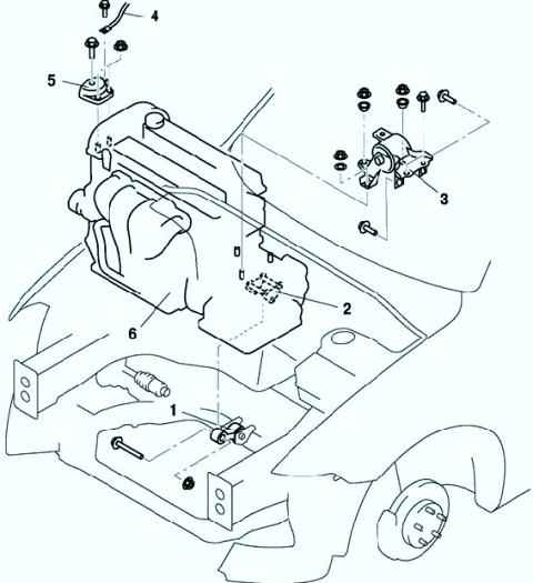
Mount the engine and gearbox in the final drive assembly using an engine jack and accessory (fig. 4).
Remove the special tool (see fig. 1).
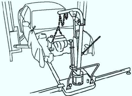
Mount the engine and gearbox in the final drive assembly using a hoist (fig. 5)
Remove #4 engine mount bracket and #4 engine mount assembly (fig. 6).
Installing engine mount bracket No. 3
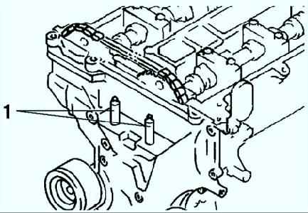
Tighten the threaded (welding) stud of the engine support bracket No. 3 with a tightening torque of 7–13 Nm (Fig. 7)
Tighten the #3 engine mount bracket bolt and nut in the order shown in Figure 8
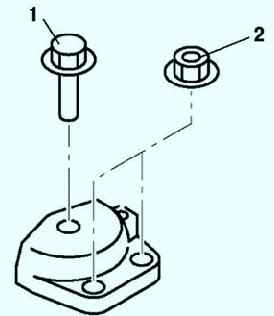
Installing No. 4 engine mount bracket and No. 4 engine mount
Tighten the #4 engine mount bracket and #4 engine mount bracket bolt and nut in the order shown in Figure 9.
Mount the engine and gearbox in the final drive assembly using an engine jack and accessory (see fig. 4)
Remove the lift and secure the engine and gearbox to the final drive using the special tool (see fig. 10)
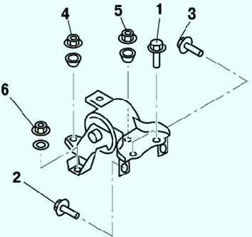
Installing support #1
Tighten bolt A of the engine support bracket to a torque of 93.1-116.6 Nm.
Tighten the bolt B of the engine mount bracket with a tightening torque of 93.1-116.6 Nm.
Tighten the tie bolt of the engine support bracket No. 1 to a tightening torque of 85.3–116.6 Nm.
Tighten the tie bolt (B) on the body with a tightening torque of 93.1 - 116.6 Nm (fig. 11).
Install other components in the reverse order of removal.
Start the engine.
Inspect for engine oil, coolant, transmission oil and fuel leaks.
Check ignition timing, idle speed and mixture.
Perform a test drive.