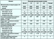
Using pulse signals from the proximity switches on the Hall sensor in the power window motor, the power window control module in the power window main switch determines the position of the window and the direction of movement of the window
Accordingly, the main switch controls the power window servo system on the driver's side.
When the home position is set before the vehicle is handed over, the window glass position and direction of operation are stored in the control module in the power window master switch.
Adjustment of the home position is therefore necessary if the cable is disconnected from the negative battery terminal, the main switch connector or the power window motor connector.
If the home position has not been set, then the functions of the automatic operation of the driver's side power window system, automatic window return and fine movement will not be available.
Power window motor
The power window motor is equipped with a connector and a gear.
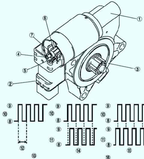
Two proximity switches on the Hall sensor are installed in the socket.
The hall-sensor proximity switch uses a set of magnets on a rotating axle to sense the rotation of the power window motor and outputs a synchronized pulse to the main power window switch.
The proximity switch on Hall sensor #1 emits one pulse per rotation of the window motor shaft.
Accordingly, the power window main switch determines the angular speed of rotation of the electric motor.
The main switch determines the direction of rotation of the power window motor by the difference between the highest and lowest points of the pulse from each proximity switch on Hall sensors No. 1 and 2.
Door lock servo system
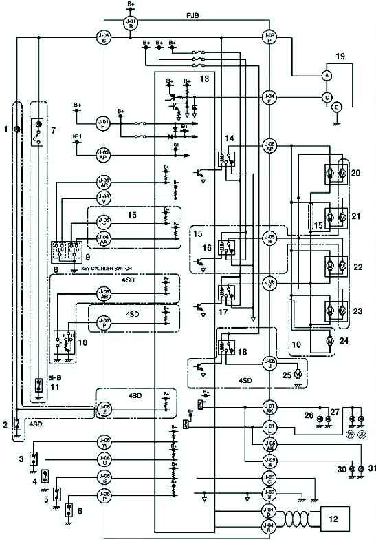
The radio transmitter is equipped with a button to turn off the alarm sensor.
The lock cylinder switch is located in the door lock retainer.
Removing and installing power window regulator
Disconnect the negative battery cable.
Remove the front door/rear door glass.
Remove the front door/tailgate speaker.
Remove the power window motor.
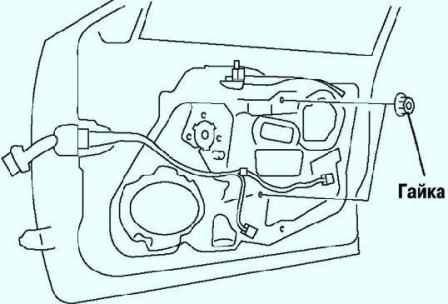
Remove the nuts (fig. 3).
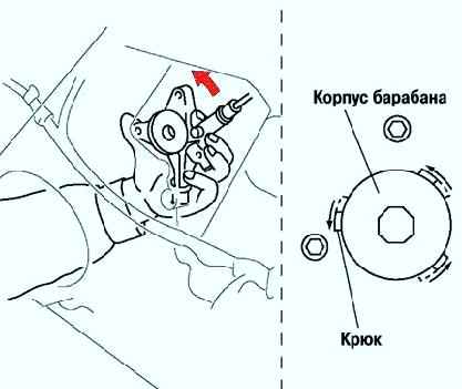
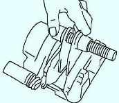
Insert your hand through the speaker hole, rotate the regulator drum housing in the direction shown in Figure 4, and separate the regulator drum housing from the door unit mounting hooks.
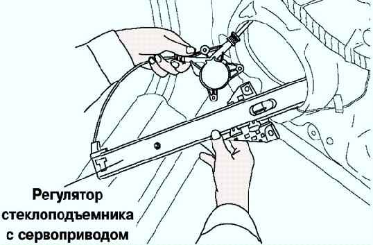
Remove the power window adjuster from the speaker mounting hole (fig. 5)
Install in reverse order of removal
Removing and installing power window motor
Disconnect the negative battery cable.
Remove the front door trim or rear door trim.
Disconnect the power window motor connector.
Remove the bolts.
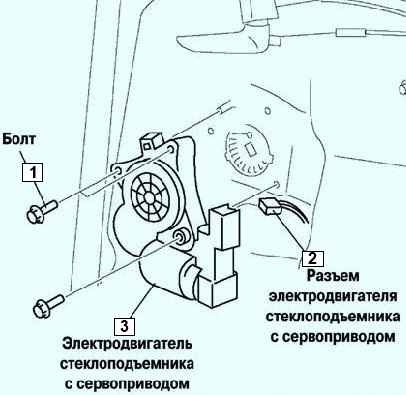
Remove the power window motor from the power window adjuster drum (fig. 6). Install in the reverse order of removal.


