The operation of the electronic automatic transmission in the final drive unit is divided into three systems: electronic control mechanism, hydraulic control mechanism and transmission mechanism (includes torque converter)
Receiving signals from switches and sensors in the input system, the Electronic Control Module (ECM) outputs a signal that matches existing driving conditions with the linear solenoid, switching solenoids, and duty cycle solenoids in the hydraulic control mechanism.
In turn, the hydraulic control mechanism, receiving signals from the PCM, switches the hydraulic channels in the control valve block and controls the clutch engagement pressure.
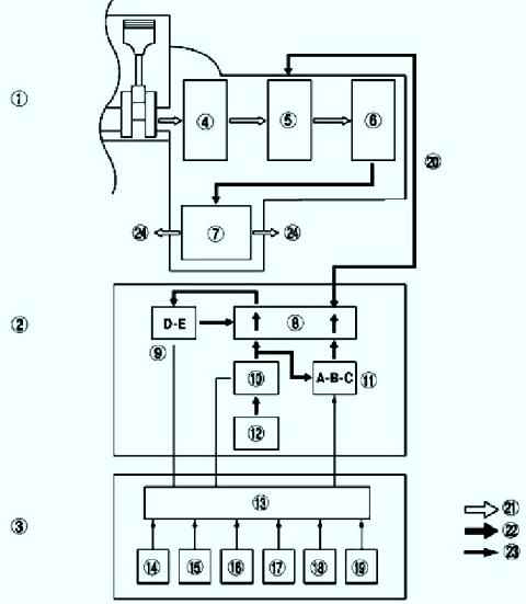
Line pressure is controlled by a linear solenoid.
The hydraulic ports are switched by the shift solenoids (shift solenoids D and E), the clutch engagement pressure is controlled by the duty cycle solenoids (shift solenoids A, B, and C) (see fig. 1).
In the transmission mechanism, the driving force from the engine is transmitted through a torque converter to the gearbox in the final drive.
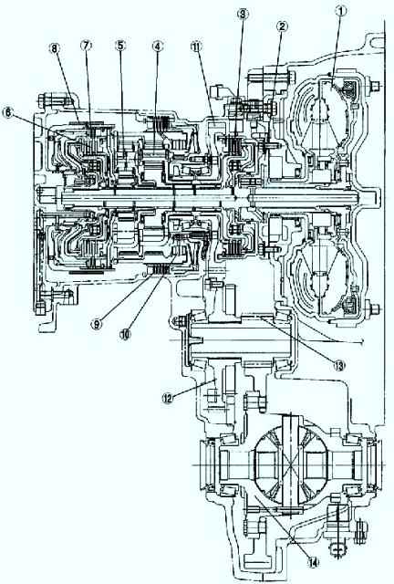
The transmitted driving force controls each clutch and brake according to the clutch engagement pressure from the duty cycle solenoids.
Planetary gears change gear ratio to optimize propulsion.
Next, the driving force is transmitted through the differential to the wheel drive shaft and then to the wheels.
The cars use four-speed automatic transmissions (AT) with the possibility of manual shifting.
The design of the automatic transmission includes a torque converter, an oil pump, planetary gears, friction clutches and brakes.
The gearbox is controlled by an electronic unit.
The torque converter acts as a clutch.
During operation, it is filled with a working fluid and, rotating at a sufficient speed, transmits torque from the transmission engine, absorbs and smoothes vibrations and jerks from the operation of the engine and gearbox.
The torque converter consists of three wheels: pumping, reactor and turbine, this also includes its blocking clutch.
The pump wheel is integrated with the torque converter housing and fixed to the engine flywheel.
The turbine wheel is splined to the gearbox input shaft.
After reaching a certain speed, the torque converter is blocked using the clutch, while ensuring a rigid connection between the engine crankshaft and the transmission.
This significantly reduces power loss and has a positive effect on driving dynamics and fuel consumption.
The oil pump is driven by the engine and is designed to sense the necessary pressure of the working fluid for the operation of the automatic transmission. This is the reason for the impossibility of starting the engine of a car with automatic transmission “from the pusher”.
In the absence of fluid pressure, the torque from the transmission cannot be transferred to the engine crankshaft in any way
Also, the lack of pressure of the working fluid imposes certain restrictions on the towing of the car, since there is no proper lubrication of the automatic transmission units.
Planetary mechanisms are installed directly in the automatic transmission case and are designed to provide a change in gear ratio and reverse gear engagement.
The planetary mechanism (transmission) consists of four main elements: the sun gear, the carrier with satellites and the ring gear.
Changing the gear ratio and direction of rotation occurs by locking or unlocking two of the three elements (sun gear, carrier, ring gear) in various combinations.
In modern automatic transmissions, several planetary gears are installed, depending on the number of gears and design.
Friction clutches and brakes are designed to block various elements of planetary mechanisms.
They are triggered by the pressure of the working fluid when the corresponding valve is opened.
The valves open in a certain sequence by the electronic control unit, depending on the speed, degree of throttle opening, crankshaft speed and other parameters.
Checking the technical condition
Checking the level of the working fluid in the gearbox.
A low or high fluid level can have a significant effect on the operation of the gearbox.
During the level check, we also pay attention to the condition of the working fluid.
The liquid should have a dark transparent or reddish color, without the inclusion of small particles and without a burning smell.
Otherwise, there is a serious malfunction in the gearbox and it is necessary to contact a specialist workshop as soon as possible.
We make sure that the selector cable is in good condition and correctly adjusted, as well as that the selector itself is in good condition.
The selector must be clearly fixed in all positions, while its positions must correspond to the modes to be switched on.
In addition, all blocking of the selector from its accidental movement should work properly.
If a malfunction is detected, it must be eliminated
When driving, there should be no jerks, bumps and various extraneous sounds.
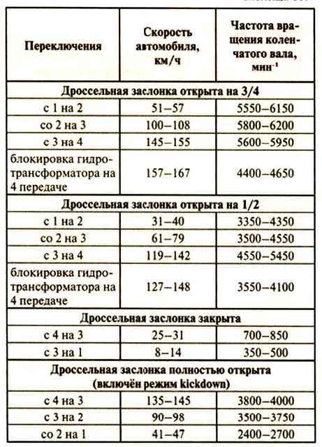
We check the correctness and timeliness of gear changes when driving in various modes (the selector is in position D) according to the table.
On the inspection ditch or overpass, we inspect the gearbox from all sides, make sure there are no oil leaks:
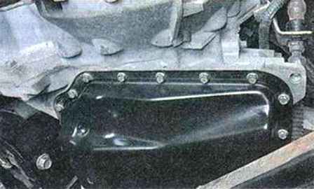
- along the perimeter of the automatic transmission pan: the presence of oil leakage indicates the need to replace the gasket.
To perform the work, it is advisable to contact a specialized service station;
- in the lower part of the junction of the torque converter housing and the engine cylinder block: the presence of traces of oil leakage indicates the need to replace the torque converter oil seal.
To perform the work, it is advisable to contact a specialized service station;
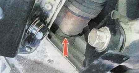
- at the junction of the gearbox with the internal hinge of the left drive and the intermediate shaft.
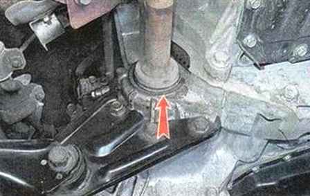
The presence of oil leakage in these places indicates the need to replace the front wheel drive oil seals


