Mazda 3 Wiring Diagrams
The electrical circuit consists of an electrical element, switches, relays, electric motors, fuses, circuit breakers, wires and connectors that connect the current consumer to the battery and body
For help in finding sources of malfunction of the electrical system, diagrams of the electrical equipment of the car are given
Before attempting to determine the source of a malfunction, study the appropriate electrical circuit diagram to get an idea of \u200b\u200bthe elements of this circuit.
The number of possible sources of malfunction can be reduced by checking the operation of other elements included in this circuit.
If several elements or circuits fail at the same time, the fuse common to these circuits or elements may be defective, or the connection to the body - “ground” is broken.
The causes of the malfunction are loose or oxidized connectors, poor contact with the body, blown fuses or faulty relays.
Visually check the condition of all fuses, wires and connectors in the failed circuit before proceeding to check the rest of the elements.
Use the wiring diagrams to determine the end clamps that need to be checked to determine the source of the problem.
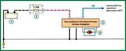
Scheme 1. Cooling system: 1 - battery, 2 - mounting block and relay in the engine compartment, 3 - control unit for the electric fan of the cooling system, 4 - electric fan of the cooling system
Scheme 2. Fuel supply system: 1 - battery, 2 - mounting block of relays and fuses in the engine compartment, 3 - fuel pump relay, 4 - fuel pump
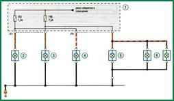
Scheme 3. Marker lights: 1 - mounting block in the cabin, 2 - left headlight (marker lamp), 3 - right headlight (marker lamp), 4 - left rear lamp (parking lamp), 5 - right tail lamp (gauge), 6 - license plate lights.
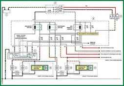
Scheme 4. Headlight unit: 1 - battery, 2 - mounting block in the engine compartment, 3 - ignition switch, 4-mounting block in the passenger compartment, 5 - left steering column switch, 6 - left headlight high beam, 7 - left headlight low beam, 8 - left headlight low beam, 9 - right headlight high beam, 10 - right headlight low beam, 11 - right headlight high beam


