")
")
")
")
")
")
The car uses DC electrical equipment with a rated voltage of 12 V
The electrical equipment of the car is made according to a single-wire circuit: the negative terminals of the sources and consumers of electricity are connected to the "ground", which acts as a second wire. In turn, the role of the "mass" is performed by the body of the car.
Consumers are powered by a battery (when the engine is not running) and a generator (when the engine is running).
A feature of the electrical circuit is the connection of a number of elements (window washers, interior lights, door locks, etc.) through the electronic control unit for the interior electrical equipment and anti-theft alarm.
The electronic unit allows you to delay turning on and off electrical appliances, change the duration of the pause in their work, depending on the selected control algorithm.
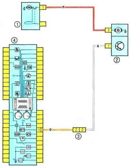
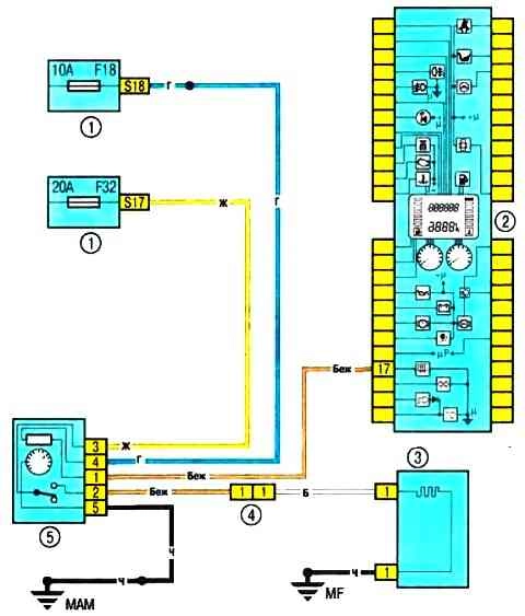
Scheme 1. Battery charging circuit
Scheme 2. Fuel pump and fuel level sensor
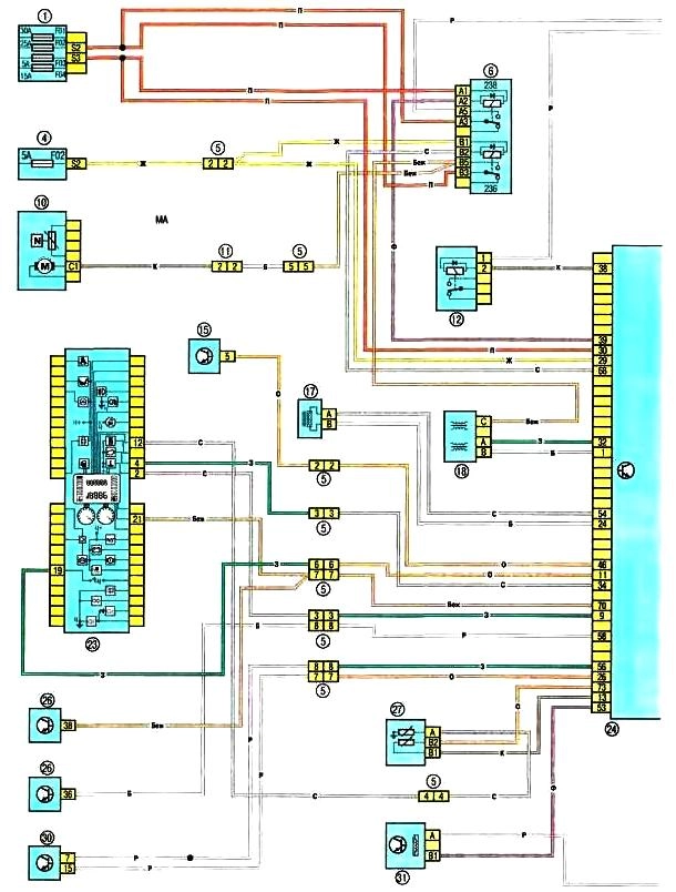
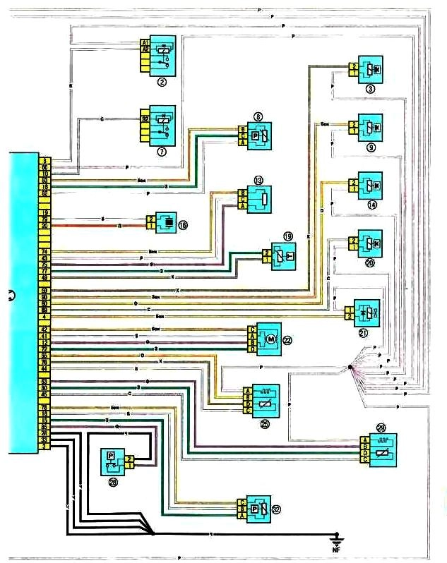
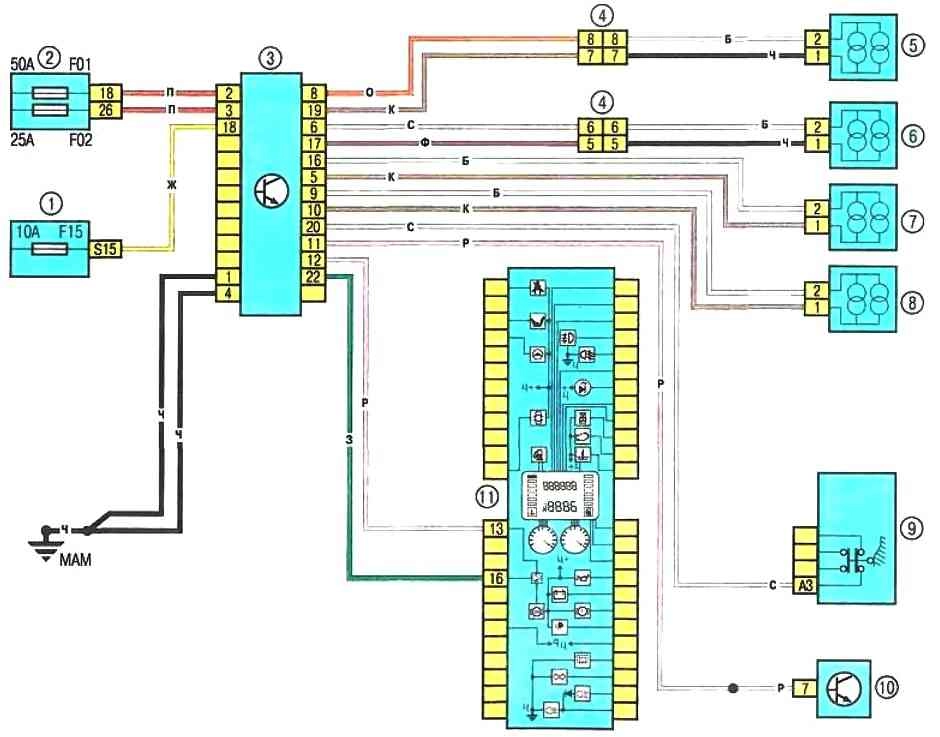
Schemes 3, 4 Engine control system: 1 - fuse box 5978 in the engine compartment (see Fig. 10.2a and 10.2b); 2 - relay block 784 in the engine compartment, relay 700; 3 - nozzle of the first cylinder; 4 - fuse block in the passenger compartment (see Fig. 10.1); 5 - electrical wiring connector of the engine compartment / interior (monoblock); 6 - relay block 1047 in the engine compartment, relays 236 and 238; 7 - relay block 784 in the engine compartment, relay 474; 8 - coolant pressure sensor (cars with air conditioning); 9 - nozzle of the second cylinder; 10 - fuel pump and fuel level sensor; 11 – a socket of electroconducting of the panel of devices / the left back part of a body; 12 - relay block in the engine compartment, relay 234; 13 - throttle position sensor; 14 - nozzle of the third cylinder; 15 – the control panel of the conditioner; 16 - knock sensor; 17 - crankshaft position sensor; 18 - ignition module; 19 - air temperature sensor; 20 - nozzle of the fourth cylinder; 21 - adsorber; 22 - stepper motor of the idle speed controller; 23 – a combination of devices; 24 - ECU; 25 - diagnostic oxygen concentration sensor; 26 - cabin switching unit; 27 - coolant temperature sensor; 28 - pressure switch of the power steering system; 29 - oxygen concentration sensor of the engine management system; 30 - diagnostic connector; 31 - speed sensor; 32 - absolute pressure sensor in the intake pipe
Scheme 3, 4. Schemes of the engine control system
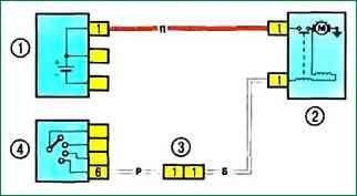
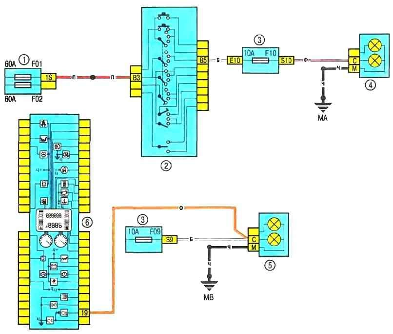
Scheme 5. Engine start system: 1 - battery; 2 - starter; 3 - electrical wiring connector of the engine compartment / interior (monoblock); 4 - ignition switch
Scheme 5. Engine start system
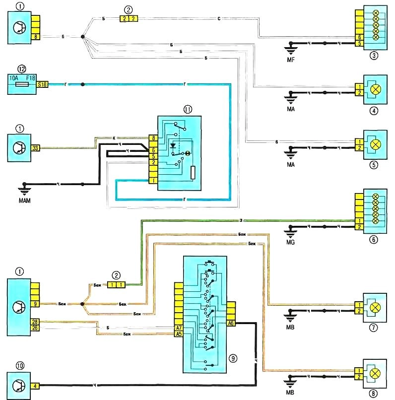
Scheme 6. Direction indicators and alarms: 1 - passenger compartment switching unit; 2 - dashboard wiring connector and / left rear of the body; 3 – the right back lantern; 4 - right front direction indicator; 5 – the right repeater of the index of turn; 6 – the left back lantern; 7 - left front direction indicator; 8 – the left repeater of the index of turn; 9 - lever switch for outdoor lighting and direction indicators with a button for turning on the sound signal; 10 - diagnostic connector; 11 - alarm switch; 12 - fuse box in the cabin
Scheme 6. Direction indicator and alarm
Diagnosis of malfunctions of on-board electrical equipment
A typical electrical circuit may include a main electrical element, various switches, relays, electric motors, fuses, fuses or circuit breakers related to this element, wiring and connectors used to connect the main element to the battery and ground body.
Before you begin troubleshooting any electrical circuit, carefully study the relevant diagram to understand its function as clearly as possible.
The circle of troubleshooting is usually narrowed by gradually identifying and eliminating normally functioning elements of the same circuit.
If several elements or circuits fail at the same time, the most likely cause of the failure is a blown fuse or a broken contact with the "ground" (different circuits in many cases can be closed to one fuse or ground terminal).
Electrical equipment failures are often due to the simplest causes, such as corrosion of connector contacts, fuse failure, fuse blown, or relay damage.
Visually check the condition of all fuses, wiring, and connectors in the circuit before proceeding to a more detailed check of the health of its components.
When using diagnostic tools for troubleshooting, carefully plan (in accordance with the attached electrical diagrams) where and in what sequence the device should be connected in the loop for the most effective troubleshooting.
The main diagnostic tools include an electrical circuit tester or voltmeter (you can also use a 12-volt test lamp with a set of connecting wires), an open circuit indicator (probe) that includes a lamp, its own power source and a set of connecting wires.
In addition, you should always have a set of wires in the car for starting the engine from an external source (the battery of another car), equipped with crocodile clips and preferably an electrical circuit breaker.
They can be used for shunting and connecting various elements of electrical equipment when diagnosing a circuit. As already mentioned, before proceeding to check the circuit using diagnostic equipment, determine the connection points from the diagrams.
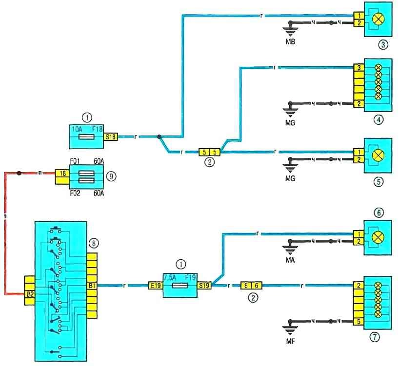
Scheme 7. Position light: 1 - fuse box in the passenger compartment: 2 - electrical connector for the instrument panel / left rear of the body; 3 – dimensional light of the left headlight; 4 – the left back lantern; 5 - license plate light; 6 – dimensional light of the right forward headlight; 7 – the right back lantern; 8 - lever switch for outdoor lighting and direction indicators with a button to turn on the sound signal; 9 - fuse box 597A in the engine compartment
Scheme 8. High beam
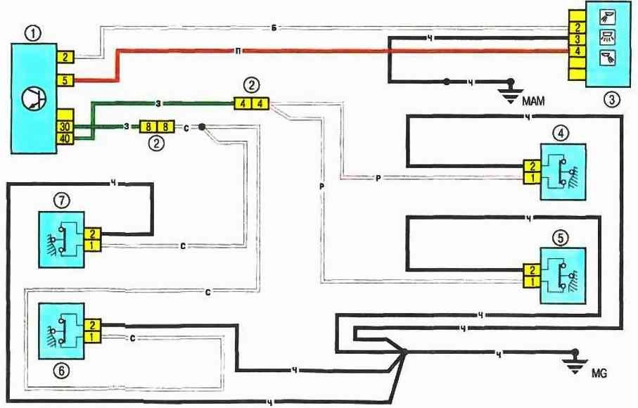
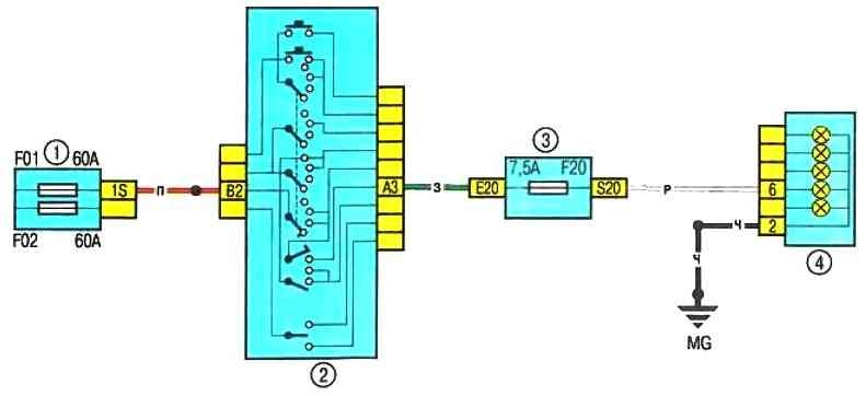
Scheme 9. Electric heating of the rear window: 1 - fuse block in the cabin: 2 - instrument cluster; 3 - electric heating of the rear window; 4 – a socket of electroconducting of the panel of devices / the left back part of a body; 5 - rear window electric heating switch
Scheme 9. Electric heating of the rear window
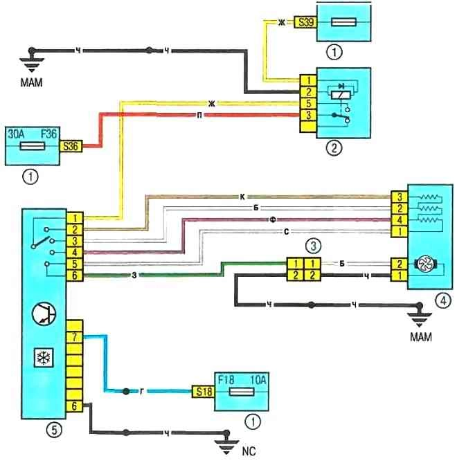
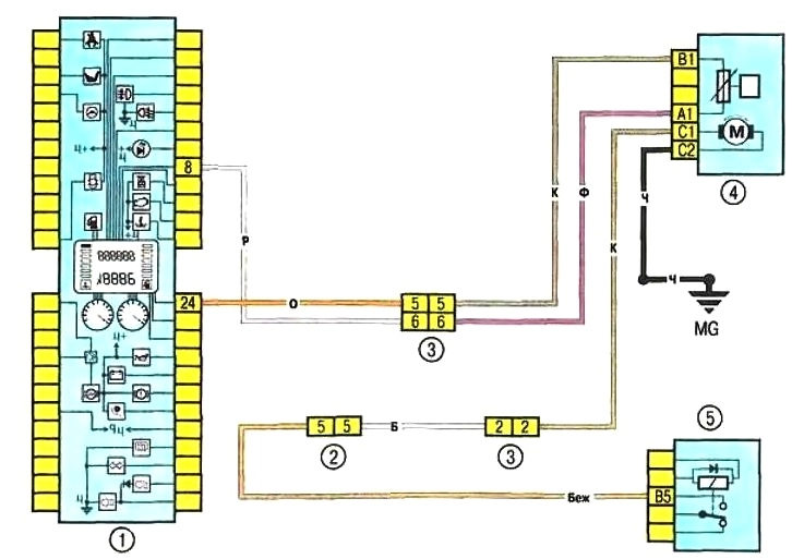
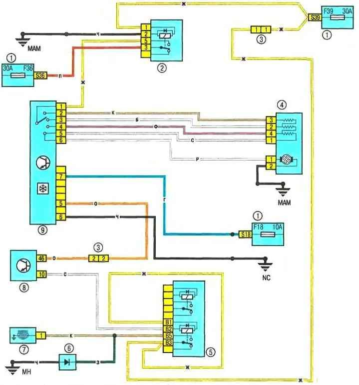
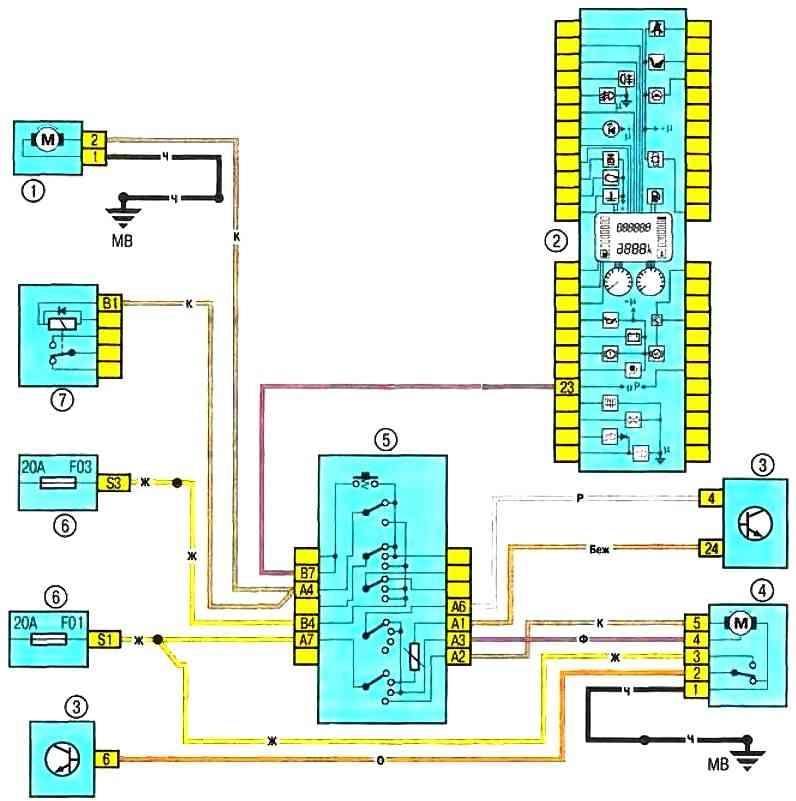
Scheme 10. electric fan of the interior heating and ventilation system: 1 - fuse box in the cabin; 2 - relay 233; 3 - connector for wiring the electric fan of the cooling system / instrument panel; 4 - electric fan of the heating and ventilation system; 5 - control unit for the heating and ventilation system
Scheme 10. Electric fan of the interior heating and ventilation system
Scheme 11. Front fog lights: 1 - instrument cluster: 2 - switch lever for outdoor lighting and direction indicators with a signal button; 3 - fuse box in the cabin; 4 - relay block 299 in the engine compartment; 5 – a socket of electroconducting of the panel of devices / fog lamps; 6 - left fog lamp; 7 - right fog lamp
Scheme 11. Front fog lights
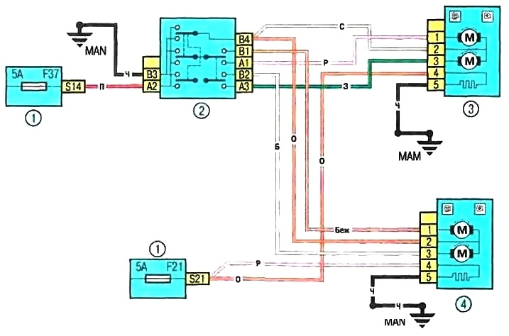
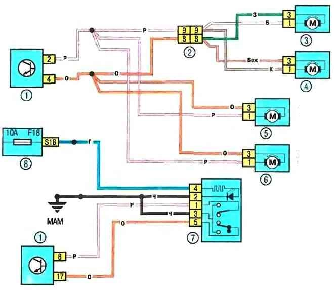
Scheme 12. Power mirrors: 1 - fuse box in the cabin; 2 - control unit for external rear-view mirrors; 3 - electric drive of the left external rear-view mirror with electric heating; 4 - electric drive of the right outside rear-view mirror with heating
Scheme 12. Power mirrors
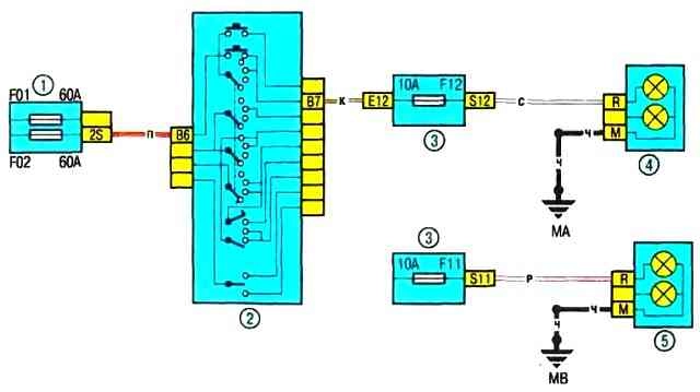
Scheme 13. Dipped beam: 1 - fuse box 597A in the engine compartment; 2 – the lever of switches of external illumination and indexes of turn; 3 - fuse box in the cabin; 4 - right front headlight; 5 - left front headlight; 6 - instrument cluster
Scheme 13. Dipped beam
Checks for the presence of supply voltage are carried out in case of an electrical circuit failure.
Connect one of the circuit tester wires to the negative battery terminal or make good contact with the vehicle body.
Connect the other tester lead to the terminal of the circuit being tested, preferably closest to the battery or fuse.
If the tester's control lamp lights up, there is supply voltage on this section of the circuit, which confirms the health of the circuit between this point of the circuit and the battery.
In the same way, explore the rest of the chain. Detection of a supply voltage failure indicates a fault between this point in the circuit and the last one tested earlier (where the supply voltage was).
In most cases, the cause of failure is loosening of the connectors and damage to the contacts themselves (oxidation).
Searching for a short circuit
One of the methods for finding a short circuit is to remove the fuse and connect a probe lamp or voltmeter instead. There should be no voltage in the circuit.
Pull the wiring while watching the probe lamp. If the lamp starts flashing, there is a short to ground somewhere in this wiring harness, possibly caused by chafing of the wire insulation.
A similar test can be carried out for each of the components of the electrical circuit by turning on the appropriate switches.

Scheme 14. Power windows of the front doors: 1 - power window switch of the front passenger door; 2 – the electric motor of a window regulator of a forward passenger door; 3 – the electric motor of a window regulator of a door of the driver; 4 - fuse box in the cabin; 5 - impulse switch for power windows of the driver's door
Scheme 14. Power windows of the front doors
Scheme 15. Electric fan of the heating (air conditioning) and interior ventilation system: 1 - fuse box in the cabin; 2 - relay 233; 3 - electrical wiring connector of the engine compartment / interior (monoblock); 4 - electric fan of the heating and ventilation system; 5 - relay block 784 in the engine compartment; 6 - diode of the air conditioner and power steering; 7 - electromagnetic clutch of the air conditioner compressor; 8 - ECU; 9 - control unit for the heating and ventilation system
Scheme 15. Electric fan of the heating (air conditioning) and interior ventilation system
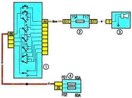
Scheme 16. Sound signal
Scheme 17. Central locking system: 1 - passenger compartment switching unit; 2 – a socket of electroconducting of the panel of devices / the left back part of a body; 3 – the electric drive of the lock of the right back door; 4 - electric lock of the left rear door; 5 - electric lock of the right front door; 6 - electric drive of the driver's door lock; 7 – the switch of system of the central blocking of locks; 8 - fuse box in the cabin
Scheme 17. Central locking system
Scheme 18. ABS control system: 1 - fuse block in the passenger compartment; 2 - fuse box 597C in the engine compartment; 3 - ABS ECU; 4 – a socket of conducting of the panel of devices / the left back part of a body; 5 - sensor for the speed of rotation of the right rear wheel; 6 - left rear wheel speed sensor; 7 - speed sensor of the left front wheel; 8 - speed sensor of the right front wheel; 9 – stoplight switch; 10 - diagnostic connector; 11 - instrument cluster
Scheme 18. ABS control system
Checking the reliability of contact with the "ground"
Disconnect the battery and connect one of the wires of a probe lamp with an independent power source to a point with known good contact with ground.
Connect the other lamp wire to the wire harness or connector pin you are testing.
If the lamp lights up, ground contact is OK (and vice versa).
An open circuit test is used to detect open circuits.
After disconnecting power to the circuit, test it with a self-powered test lamp.
Connect the probe leads to both ends of the circuit. If the control lamp lights up, there is no open circuit.
If the lamp does not light up, then this indicates an open circuit in the circuit.
Similarly, you can check the health of the switch by connecting the probe to its contacts.
When the switch is turned to the "ON" position, the probe lamp should light up.
Localize the breakpoint
When diagnosing an open section of an electrical circuit, it is quite difficult to visually detect the cause of the malfunction, since it can be difficult to visually check the terminals for corrosion or a deterioration in the quality of their contacts due to limited access to them (usually the terminals are closed by the contact connector housing) .
A sharp twitch of the body of the wiring harness block on the sensor or the wiring harness itself in many cases leads to contact restoration.
Keep this in mind when trying to isolate the cause of a circuit failure that is suspected to be open.
Unstable failures may be due to oxidation of the terminals or poor quality of the contacts.
Scheme 19. Windshield wiper and washer, headlight washer: 1 - windshield washer pump; 2 – a combination of devices; 3 – cabin switching unit; 4 – electric motor of a cleaner of a windshield; 5 – windshield wiper and washer switch lever with on-board computer display modes button; 6 - fuse box in the cabin; 7 - relay block 299 in the engine compartment, relay 753
Scheme 19. Windshield wiper and washer, headlight washer
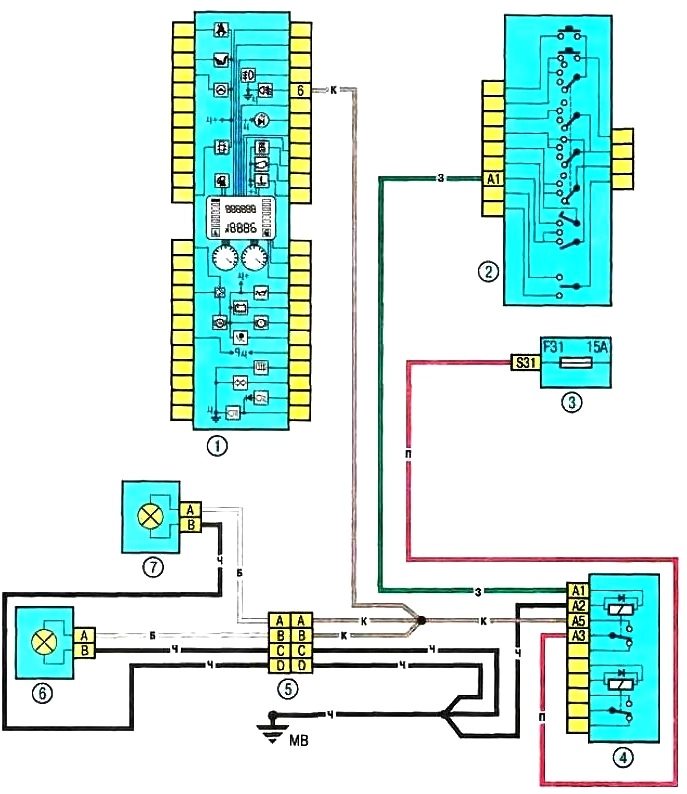
Scheme 20. Car interior lighting dome: 1 - interior switching unit; 2 – a socket of electroconducting of the panel of devices / the left back part of a body; 3 - dome light interior; 4 – the limit switch of a door of the driver; 5 - limit switch of the right front door; 6 – the limit switch of the right back door; 7 - limit switch of the left rear door
Scheme 20. Interior lampshade.
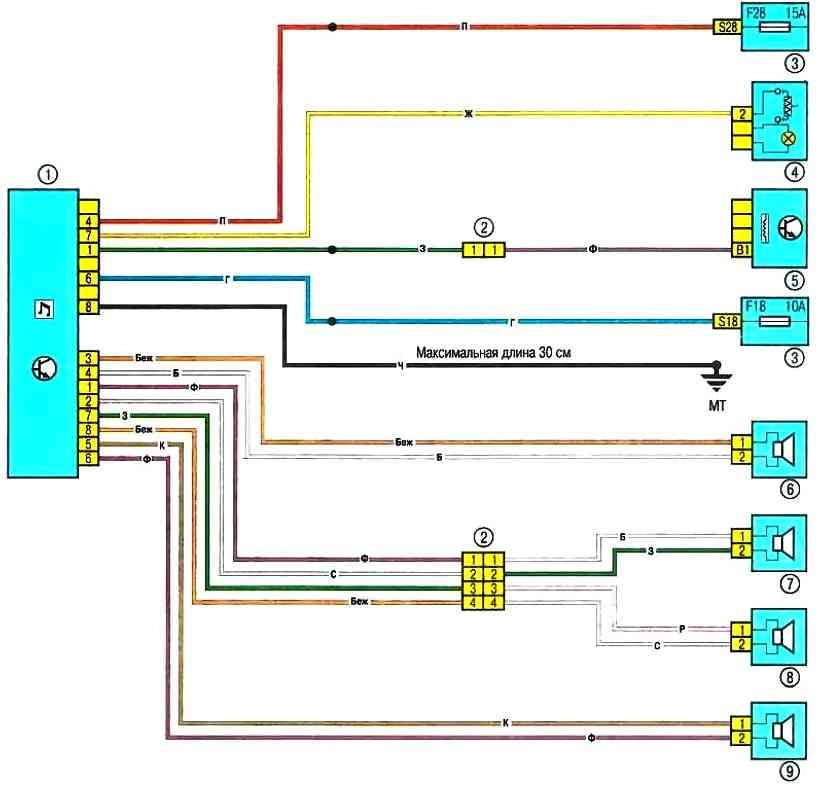
Scheme 21. Connecting the speakers of the acoustic system: 1 - car radio; 2 - electrical connector of the engine compartment / interior (monoblock); 3 - fuse box in the cabin; 4 - cigarette lighter; 5 - vehicle speed sensor; 6 - right front speaker; 7 - right rear speaker; 8 - left rear speaker; 9 - left front speaker; 10 - electrical wiring connector of the instrument panel / left rear of the body
Scheme 21. Connecting the speakers of the acoustic system.
Scheme 22. Rear fog lamp: 1 - fuse box 597A in the engine compartment; 2 - lever switch for outdoor lighting and direction indicators with a button for turning on the sound signal; 3 - fuse box in the cabin; 4 - left rear light
Scheme 22. Rear fog lamp.