In the article, we will consider the replacement of sensors and switches
We discussed the replacement of engine control system sensors in the article - Removing and installing elements of the Toyota Camry engine control system
Oil pressure drop sensor replacement
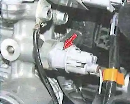
The oil pressure warning light sensor is screwed into the cylinder block wall at the rear (next to the coolant temperature sensor)
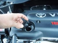
Remove the decorative engine cover
Disconnect the negative battery terminal
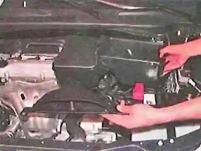
Remove the air filter with the air intake
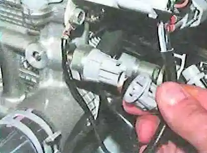
Squeeze the latches and disconnect the wire block from the sensor
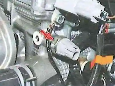
Unscrew the sensor from the cylinder block
Install the oil pressure drop sensor in reverse order
Checking and replacing the fuel gauge sensor
Fuel gauge sensor installed in the fuel module
We reduce the fuel pressure, as indicated in the article - Checking and reducing the fuel pressure of the 2AZ-FE engine of a Toyota Camry car
Disconnect the negative battery cable
We remove the fuel module, as described in the article - Removing and disassembling the fuel module of a Toyota Camry car
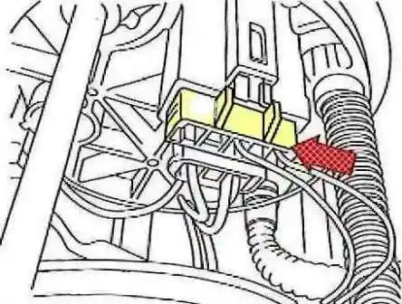
Disconnect the fuel gauge sensor wire block from the fuel module flange
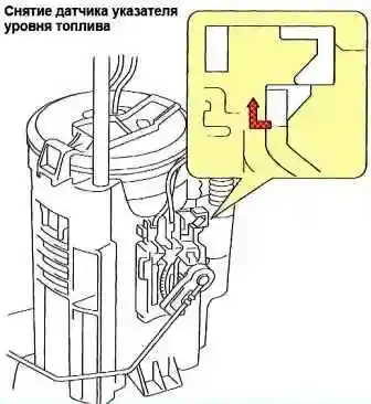
Unfasten the latch and remove the sensor from the fuel module body
To check the sensor, we connect the tester in ohmmeter mode to the terminals "2" ("S") and "3" ("FE") of the sensor
We measure the resistance of the sensor at the lower position of the lever with the float. The resistance should be 405.5-414.5 ohms
Raise the lever with the float to its highest position - the resistance should decrease to 13.5-16.5 Ohm
If the resistance of the sensor differs from the given values, then the sensor is defective and needs to be replaced
Install parts in reverse order
Checking and replacing the automatic transmission shaft speed sensors
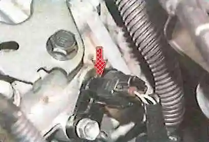
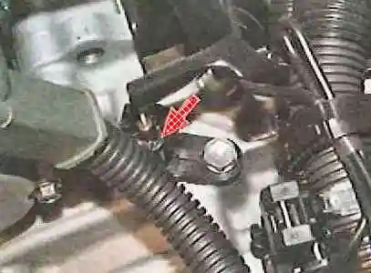
Torque converter turbine wheel speed sensors and gearbox output shaft speed sensors are installed in the upper part of the gearbox housing

Remove the battery and air filter with air intake
Squeeze the latches and disconnect the wire block (B) from the sensor to be replaced
We unscrew the bolt (A) and remove the sensor from the hole in the gearbox housing
To check the sensor, we measure the resistance between the contacts.
At +20º C, the resistance should be 560-680 ohms. If the resistance is different, then the sensor is defective
If the sealing ring of the sensor is damaged, then we replace it
Install the sensor in reverse order
Replacing the automatic transmission selector position sensor

The sensor is installed in the lower part of the gearbox housing (in front of the vehicle)
We prepare the car and disconnect the negative battery terminal
Remove the air filter with the air intake
If we install the same sensor, then before removing it, you need to mark the position of the sensor relative to the gearbox housing

Unscrew the nut 1 and disconnect the cable from the gear lever 2
Unscrew the nut 3 and remove the gearshift lever 2 from the shaft
We bend the antennae of the lock washer 5 and unscrew the lock nut 6. Remove the lock washer from the shaft
Squeeze the latches and disconnect from the position sensor of the automatic transmission selector block 7 of the wiring harness
Remove the sensor from the gearbox by unscrewing its fastening bolts 4 and 8
Installation
We install the selector position sensor on the gearbox without finally tightening the bolts 4 and 8
Connect the block of wires 7 to the sensor
Install a new lock washer 5 and tighten the locknut 6 to 6.9 Nm
Install the lever 2, tighten the nut 3 to a torque of 13 Nm and bend the tab of the lock washer.
Raise the lever up to the stop, and then lower it down two clicks

Without changing the position of the lever, turn the sensor body so that the tab of the lock washer (shown by the arrow) is directed along the neutral line applied to the sensor body (highlighted in red in the photo).
In this position, tighten the sensor mounting bolts
Install all removed parts in reverse order
Make sure the engine starts only in the "N" and "P" positions of the selector, and the reverse light turns on in the "R" position and does not turn on in other positions
If malfunctions are found, we repeat the adjustment of the position of the automatic transmission selector position sensor
Replacing the brake light switch
The brake light switch is mounted on the brake pedal bracket
Disconnect the negative battery terminal

Remove the lower decorative shield
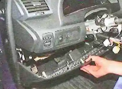
Disconnect the wiring harness from the brake light switch and unscrew the switch from the brake pedal bracket
Installation
We screw the brake light switch into the bracket until the end of the working part of its body stops against the brake pedal buffer, and then unscrew it a quarter of a turn
If the brake light switch is installed correctly, with the brake pedal released, there should be a gap of 1.5-2.5 mm between the end of the threaded part of the switch and the brake pedal buffer
Install all removed parts in reverse order
Replacing the automatic wiper control sensor
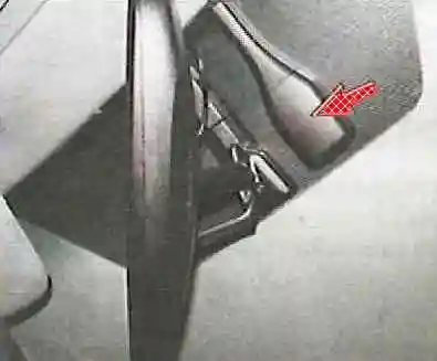
An automatic wiper control sensor (rain sensor) is installed on the inside of the windshield next to the rearview mirror
Disconnect the negative battery terminal
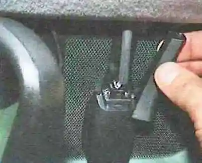
Remove the sensor cover
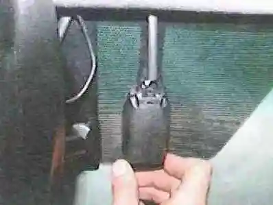
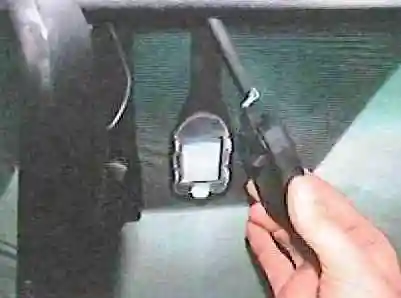
We pull out the stopper of the sensor housing and disconnect the sensor from the mounting bracket
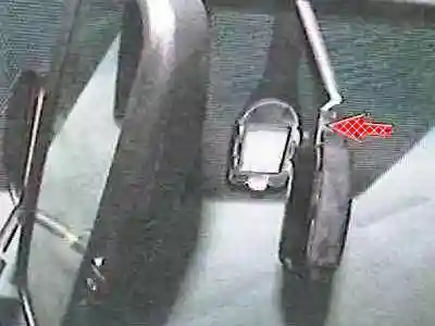
Remove the wiper automatic control sensor by disconnecting the wire block from it
Install parts in reverse order
Replacing doorway light switches
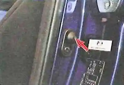
The doorway light switches are installed in the holes in the door pillars of the body
Disconnect the negative battery terminal

We unscrew the fastening screw and remove the doorway illumination switch from the hole in the pillar
Disconnect the wiring harness and remove the switch
Install the switch in reverse order
Immobilizer
The immobilizer consists of an electronic control unit, an antenna unit in the ignition lock (transponder ring), keys and a signal lamp in the display unit
The immobilizer control unit is installed on the left under the instrument panel and connected to the electronic engine control unit
When the ignition is turned on, the immobilizer control unit receives a password code from the antenna unit, which is compared with the information stored in the computer memory
Based on the result of the code analysis, the immobilizer control unit decides on the possibility of starting the engine and transmits the appropriate command to the engine controller
If the immobilizer electronic unit is replaced, it is necessary to perform the ignition key learning procedure, otherwise it will not be possible to start the engine
Replacing the mirror control unit, the headlight electrocorrector control and the headlight washer switch

Remove the decorative lower shield and instrument panel trim to the left of the steering column
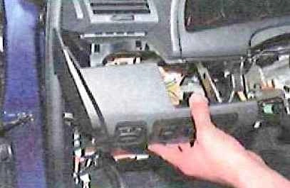
To replace the rear-view mirror control unit, the headlight electrocorrector control or the headlight washer switch, disconnect the wire blocks A, B and C from them, respectively, by squeezing the clamps
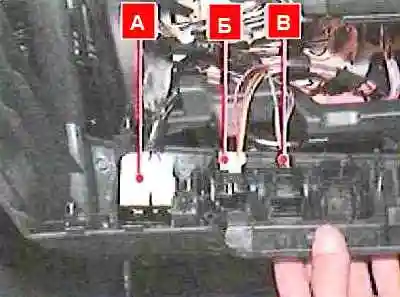
Squeeze the latches and remove the element to be replaced from the hole in the instrument panel lining
Hazard switch replacement
Disconnect the negative battery terminal
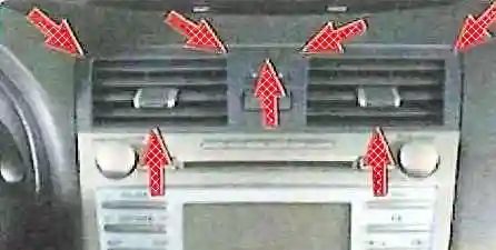
Using a puller, we release the seven latches and remove the central air duct panel with deflectors from the instrument panel
Disconnect the wire block from the alarm switch and remove the switch, releasing the four latches
Install parts in reverse order


