A part of the Toyota Camry is equipped with a 2GR-HE gasoline engine (3.5 l) - four-stroke, six-cylinder, V-shaped, with four valves per cylinder, with distributed fuel injection
The order of operation of the engine cylinders is 1-2-3-4-5-6.
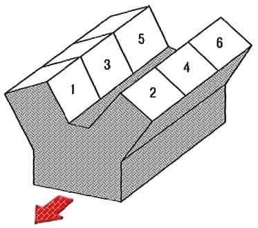
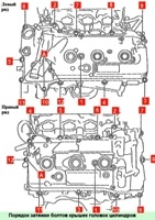
Cylinder numbering scheme is shown in the figure
A frame with intake and exhaust camshafts is mounted on top of each cylinder head of the 2GR-FE engine.
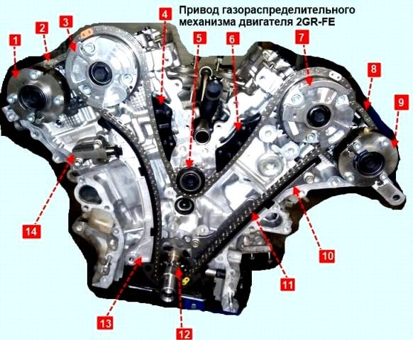
Intake camshafts are driven by roller chain 11
The tension of the chain is provided by the automatic tensioner 14 through the shoe 13
The exhaust camshafts are driven by the intake camshaft timing mechanisms 3 and 7 by single row roller chains 2 and 8
To adjust the tension of chains 2 and 8, automatic hydraulic tensioners are installed in the heads of the block.
The valves are driven from the cams of the distribution pads through levers with rollers, one shoulder resting on the hydraulic compensators.
Thanks to the hydraulic compensators on the 2GR-FE engine, it is not necessary to check and adjust valve clearances.
Camshafts are installed in bearing beds made in special frames and secured with covers
The camshafts are provided with oil channels through which oil under pressure enters the mechanisms of the variable valve timing system
The camshaft frames are bolted to the top of the cylinder heads.
Engine block
The cylinder block is a single casting that forms the cylinders, the cooling jacket, the upper part of the crankcase and four crankshaft bearings made in the form of crankcase baffles
The block is made of aluminum alloy with non-removable cast iron cylinder liners.
Crankshaft main bearing caps machined complete with block and non-interchangeable
The cylinder block has special lugs, flanges and holes for fastening parts, components and assemblies.
The crankshaft, forged from special steel, rotates in main bearings with thin-walled steel liners with an anti-friction layer.
The axial movement of the crankshaft is limited by two half rings installed in the grooves of the bed of the second main bearing.
At the front end of the crankshaft there is a target disk for the crankshaft position sensor of the engine management system.
Pistons are made of aluminum alloy. On the cylindrical surface of the piston head there are annular grooves for two compression rings and a composite oil scraper ring.
Floating type piston pins (installed in the piston bosses and in the upper heads of the connecting rods with clearance)
The piston pins are secured against axial movement by retaining rings installed in the grooves of the pin holes in the piston skirts, and are pressed into the upper heads of the connecting rods with an interference fit
Steel connecting rods, forged, with an I-section shank.
The lower heads, the connecting rods are connected to the connecting rod journals of the crankshaft through thin-walled liners, the design of which is similar to that of the main ones.
The cylinder heads are made of aluminum alloy in a transverse cylinder scavenging pattern (inlet and outlet ports are located on opposite sides of the head).
Saddles and valve guides are pressed into the heads
The intake and exhaust valves are equipped with one spring each, fixed through the plate with two crackers.
Hydraulic compensators are installed in the holes of the cylinder head.
The separation planes of the heads and the cylinder block are sealed with gaskets, each of which consists of two plates molded from thin sheet metal and welded together by spot welding.
The variable valve timing system dynamically adjusts the position of the camshafts fishing.
This system allows you to set the optimal valve timing for each moment of engine operation, which, in turn, achieves increased power, better fuel efficiency and less exhaust toxicity.
The solenoid valve, consisting of an electromagnet and a valve, which, in turn, consists of a spool and a spring, supplies oil under pressure from the main line of the lubrication system to one of the working cavities of the mechanism and drains the oil from another cavity at the signals of the electronic engine control unit , which leads to the mutual movement of the elements of the mechanism and, as a result, to a dynamic change in the position of the camshaft.
While the engine is idling, the electronic engine control unit repeatedly activates the solenoid valve for short periods of time in order to clean its elements and channels from contaminants that accidentally get into them.
When the power supply to the variable valve timing valve is turned off, the oil supply holes from the main line and the drain are fully open, and the mechanism is set to its original position.
In this case, the engine runs without changing the valve timing.
The variable valve timing system components (solenoid valve and dynamic intake camshaft position change mechanism) are precision-manufactured assemblies.
In this regard, when repairing the variable valve timing system, only the replacement of the assembled system elements is allowed.
Engine lubrication system
Lubrication system combined: the most loaded parts are lubricated under pressure, while the rest are lubricated either by directed spraying or spraying of oil flowing from the gaps between mating parts.
The pressure in the lubrication system is generated by a gear oil pump mounted outside in front of the cylinder block and driven from the front end of the crankshaft, the pump is made with an internal trochoidal gear engagement.
The pump draws oil from the oil sump through an oil receiver with a strainer and delivers it through a full-flow oil filter with a porous paper filter element to the main drain line located in the cylinder block wall
The channels for supplying oil to the main bearings of the crankshaft depart from the main line.
Oil is supplied to the connecting rod bearings through channels made in the body of the crankshaft.
The engine pistons are additionally cooled by oil supplied through special soldered nozzles of the cylinder block and sprayed onto the piston bottom.
Vertical channels for supplying oil to the camshaft bearings and to the hydraulic clearance compensators in the valve drive depart from the main oil line
To lubricate the camshaft bearings, oil from the vertical channel enters the central axial channels of the camshafts through a radial hole in the neck of one of the bearings and is distributed along them to the rest of the bearings
The camshaft cams are lubricated with oil coming from the central axial channels through the radial holes in the cams.
Excess oil is drained from the head of the block into the oil sump through vertical drainage channels.
Crankcase ventilation system
Crankcase ventilation system closed type not directly vented
Therefore, simultaneously with the suction of gases in the crankcase, a vacuum is formed in all engine operating modes, which increases the reliability of various engine seals and reduces the emission of toxic substances into the atmosphere.
The system consists of two branches, large and small.
When the engines are idling and at low load modes, when the vacuum in the intake manifold is high, crankcase gases are sucked into the intake manifold through a small branch of the crankcase ventilation system through a valve installed on the cover of the right cylinder head.
The crankcase ventilation valve opens depending on the vacuum in the intake manifold and thus regulates the flow of crankcase gases.
In full load modes, when the throttle is open at a large angle, the vacuum in the intake manifold decreases, and in the air supply hose increases.
At the same time, the main part of crankcase gases through a hose of a large branch connected to a fitting on the cover of the left head of the block enters the air supply hose, and then through the throttle assembly into the intake manifold and into the engine cylinders.
Engine cooling system
Cooling system hermetic, with expansion tank, consists of a cooling jacket made in casting and surrounding the cylinders in the block, combustion chambers and gas channels in the cylinder heads.
Forced circulation of the coolant is provided t centrifugal water pump driven by an accessory drive belt
To maintain the normal operating temperature of the coolant, a thermostat is installed in the cooling system, which covers a larger circle of the system when the engine is cold and the coolant temperature is low
The thermostat is installed in a housing connected by pipes to the cylinder heads and to the radiator.
When the coolant temperature is up to 82º C, the thermostat is completely closed and the liquid circulates through a small circuit, bypassing the radiator, which speeds up engine warm-up
At temperatures above 82º C, the thermostat starts to open and at 95 º C opens completely, allowing fluid to circulate through the radiator.
Engine power system
The power supply system consists of an electric fuel pump installed in the fuel tank, a throttle assembly, a fine fuel filter installed in the fuel pump module, a fuel pressure regulator, injectors and fuel lines
Ignition system microprocessor, consists of ignition coils, individual for each cylinder, and spark plugs.
The ignition coils are controlled by the electronic engine control unit
The ignition system does not require maintenance and adjustment during operation.
The 2GR-FE engine features a variable geometry intake manifold
In the manifold baffle there is an electrically operated damper controlled by the engine control unit.
While the engine is running at low load and low engine speed, the damper is closed and the length of the intake manifold passages is maximum
When the crankshaft speed increases or when the engine load increases, at the command of the electronic control unit, the damper opens, reducing the length of the channels.
Managing the length of the inlet piping channels allows you to improve the filling of the cylinders with air through the use of "resonant boost".
This improves engine performance and fuel efficiency.


