")
")
")
")
")
")
Vehicles equipped with a hydraulic brake system
Front disc brakes, rear disc or drum brakes
All brakes are equipped with automatic brake pad clearance adjustment.
Wear of the front disc brake pads is automatically compensated, the rear disc brake has a pad clearance adjustment mechanism.

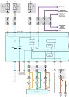
The hydraulic system consists of two separate circuits (fig. 1).
The main brake cylinder includes separate reservoirs for two circuits, in case of fluid leakage or damage in one of the hydraulic actuators, the other remains active.
A dual pressure regulator distributes hydraulic pressure between the front and rear brakes to prevent rear wheel lockup.
The brake fluid level warning is given by a warning light activated by a sensor in the master cylinder reservoir.

The parking brake (fig. 2) mechanically engages only the rear brakes.
It is activated by lifting the lever on the center console between the front seats.

The Camry has a pedal-operated parking brake option.
Vacuum brake booster

Vacuum brake booster reduces the force on the brake pedal, making driving easier.
The vacuum amplifier uses a diaphragm (Fig. 3), on both sides of which a vacuum is created during normal operation.
During braking, air is supplied from one side of the diaphragm, forming atmospheric pressure.
Due to the pressure difference transmitted through the diaphragm, the pusher moves towards rarefaction (vacuum), providing an auxiliary force for braking.
When the brake pedal is released, air is pumped out of the amplifier cavity through the control valve, creating a vacuum.
Brake Master Cylinder
The brake master cylinder is used on dual-circuit brake systems.
The front right and rear left brakes are actuated by the primary piston, while the front left and rear right brakes are actuated by the secondary piston.
The brake master cylinder combines the functions of a standard dual brake master cylinder plus a low brake fluid indicator and brake pressure regulator.
Brake pressure regulator
The pressure regulator limits the output pressure to the rear brakes after the pressure reaches the limit value in the master brake cylinder.
The regulator is used when less force is needed on the rear brakes to achieve optimal braking.
Brake fluid level sensor
The brake fluid level sensor, located in the brake fluid reservoir, turns on the BRAKE warning light when it detects a low brake fluid level.
As soon as the brake fluid level reaches the correct level, BRAKE goes out.