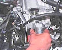
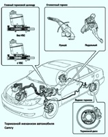
Using ETCS-i (Intelligent Electric Throttle Control System) for improved throttle control
The use of ACIS (Acoustic Intake System Control) has improved engine performance.
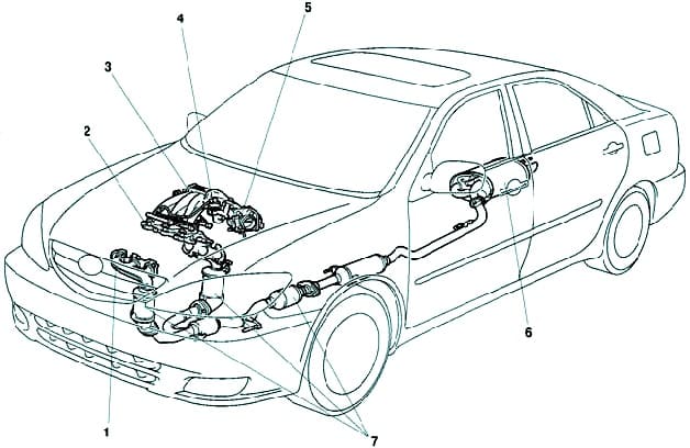
The use of an intake control system has reduced noise and improved engine performance.
A two-stage exhaust control system reduces noise and vibrations in the main muffler.
The EGR (Exhaust Gas Recirculation) system is used to reduce the concentration and control the formation of COH.
The amount of air entering the engine is determined by the throttle opening angle and engine speed.
The air flow passes through the air filter, through the throttle body passage, and into the top of the intake manifold, from where it is distributed to the engine cylinders.
When the coolant temperature is low, the idle speed control valve opens and air enters the top of the intake manifold through the bypass in addition to the air passing through the throttle.
As the engine warms up, even if the throttle is fully closed, air enters the top of the intake manifold, and therefore the idle speed (1st stage idle speed control) increases.
The upper part of the intake manifold reduces airflow pulsations.
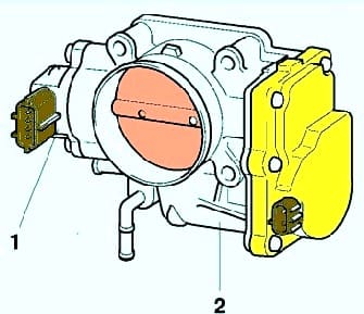
Throttle assembly
The use of the ETCS-i system without mechanical linkage provided excellent throttle control.
The throttle control uses a DC motor with minimal power consumption.
The electronic engine control unit in standby mode controls the throttle motor current to control the throttle opening angle.
Receiver
The receiver consists of upper and lower sections and has an intake air control valve.
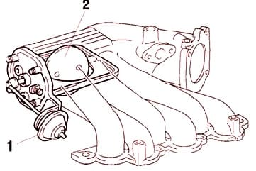
This valve is activated by ACIS (Acoustic Intake System Control) and is used to change the length of the intake pipe to improve engine performance throughout the entire speed range.
Intake manifold
Intake manifold passages have been enlarged and length optimized to improve engine performance.
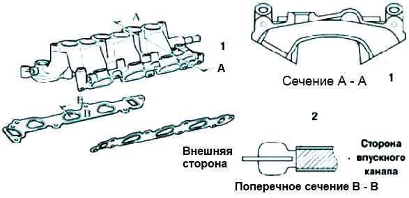
The engine cooling duct connects the left and right cylinder banks at the rear of the intake manifold (see fig. 4).
The surfaces of the intake manifold gaskets are coated with rubber, which increases their operational reliability.
Exhaust manifold
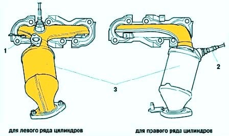
An exhaust manifold (fig. 5) made of stainless steel is used to improve the warm-up of the three-way catalytic converter and to reduce vehicle weight.
The air-fuel ratio sensor is installed in the exhaust manifold.
Exhaust system
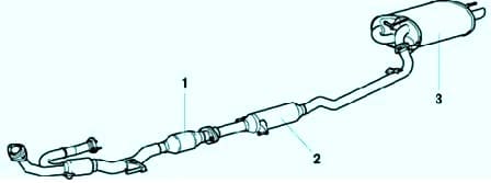
A thin-walled, high-cell ceramic three-way catalytic converter is used (Fig. 6).
This catalytic converter allowed to reduce emissions of harmful substances with exhaust gases by optimizing the cell density.
A two-stage exhaust control system reduces noise and vibrations in the main muffler.


