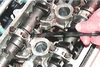
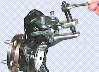
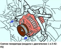
Removing the oil filter
Unscrew the oil filler cap.
Remove the PCV valve.
Remove the spark plugs.
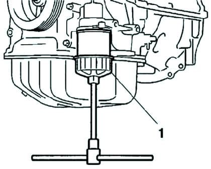
Remove the oil filter using the special tool 09228-06501 (fig. 1).
Unscrew the nut and fitting, remove the O-ring from the oil cooler, remove the radiator.
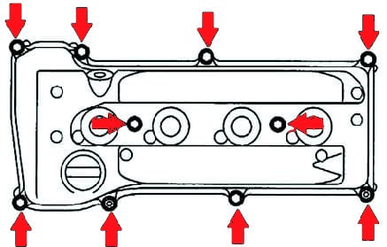
Remove the cylinder head cover with gasket by unscrewing the eight bolts and two nuts shown by the arrows in Figure 2.
Removing the crankshaft pulley
Remove the camshaft position sensor.
Set the piston of the first cylinder to TDC on the compression stroke.
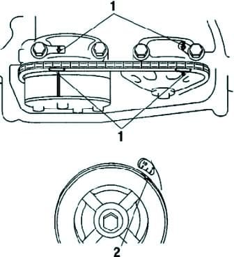
To remove the crankshaft pulley, turn it and align the mark with the “0” marking on the timing chain cover.
Make sure the marks on the sprockets are aligned with the marks on the #1 and #2 camshaft bearing caps as shown in Figure 3.
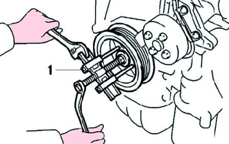
Remove the pulley bolt using a special tool, then remove the crankshaft pulley using a puller (fig. 4).
Removing the coolant pump
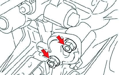
Remove the timing chain tensioner by unscrewing the two nuts shown by the arrows in Figure 5.
Remove the water pump pulley.
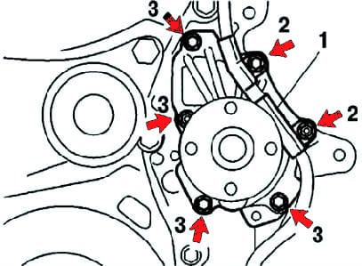
Remove the water pump by removing the four bolts and two nuts (fig. 6).
Removing the oil pan
Remove the crankshaft position sensor.
Remove the oil pan drain plug.
To remove the oil pan, unscrew the twelve bolts and two nuts.
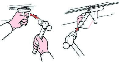
Insert the blade of the special tool 09032-00100 between the surfaces of the crankcase and the sump, cut the seal and remove the sump (Fig. 7).
Be careful not to damage the connecting surfaces of the crankcase, oil pan and timing chain cover.
Disassembling the working components of the timing mechanism drive
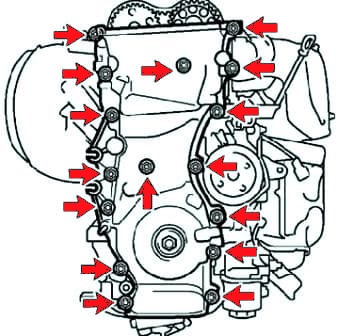
Remove the fourteen bolts and two nuts securing the timing chain cover (Fig. 8).
Use a screwdriver to separate the cover from the head and cylinder block.
Take off timing chain cover.
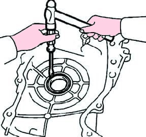
Remove the crankshaft position sensor rotor after removing the O-ring with a screwdriver (fig. 9).
Remove the timing chain guide.
Remove the timing chain tensioner shoe.
Remove the timing chain damper.
Remove the timing chain.
Remove the crankshaft sprocket.
Removing the oil pump drive chain
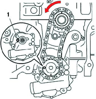
Rotate the crankshaft 90° counterclockwise and align the mark on the oil pump shaft with the hole on the pump housing as shown in Figure 10.
Insert a 4 mm pin into the hole of the shaft, fix it, and unscrew the nut.
Remove the oil pump drive chain tensioner with a spring by unscrewing the mounting bolt, then remove the sprockets and chain.
Removing the oil pump
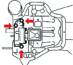
Remove the three bolts and remove the oil pump
Removing caps and camshaft bearing
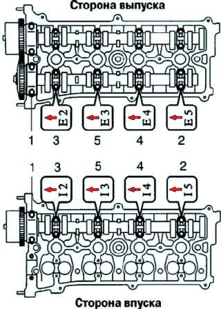
Remove the exhaust and intake camshaft covers in the order shown in Figure 12.
Remove the camshaft bearing.
Remove the VVT-i valve.
Removing the cylinder head, checking the axial play of the balancing shafts
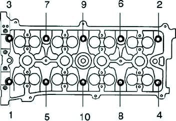
Using a 10mm socket wrench, in several passes, loosen and remove the ten cylinder head bolts in the sequence shown in Figure 13.
If the bolts are loosened in the wrong order, the cylinder head may be damaged or cracked in the cylinder head.
Remove ten washers.
Use a screwdriver to separate the head from the cylinder block.
Remove the cylinder head gasket.
Remove the oil cooler fitting.
Remove the VVT-i oil filter.
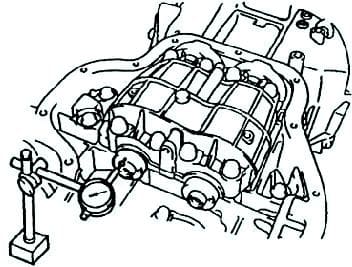
Use a dial indicator to measure the end play while moving the balance shafts back and forth (fig. 14).
Axial play of balance shafts:
- standard - 0.050-0.090 mm;
- maximum allowable - 0.090 mm.
Checking the radial play of the balance shafts
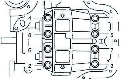
In several passes, sequentially, unscrew the eight fastening bolts and remove the cover of the balancing mechanism (Fig. 15).
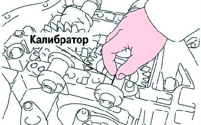
Using a plastic calibrator, measure the clearances in the plain bearings for each journal (Fig. 16).
Apply some engine oil under the heads and on the threads of the mounting bolts.
Install the balance mechanism cover.
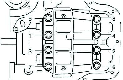
In several passes, sequentially, tighten the eight bolts securing the cover of the balancing mechanism with a tightening torque of 22 Nm (Fig. 17).
Mark the bolts with paint.
Tighten the bolts by 90° in the sequence shown in Figure 2.70.
Make sure the markings on the bolts are now at 90° from their original position.
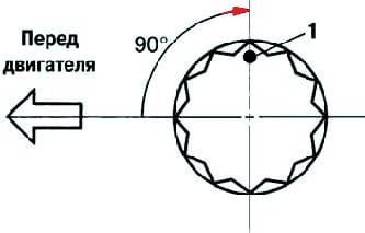
Remove the balance mechanism cover. Measure the maximum width of the flattened gauge wire to determine the radial clearance.
Radial clearance:
- standard - 0.004-0.031 mm;
- maximum allowable - 0.031 mm.
If the clearance exceeds the limit, replace the balance shaft bearings.
If the clearance is within specification, reinstall the balance shaft bearings.
When replacing standard size liners, use liners of the same size group.
There are three standard earbud sizes.
Bearing bed diameter:
- marking "1" ..... 26.000–26.006 mm;
- marking "2" ..... 26.007–26.012 mm;
- marking "3" ..... 26.013–26.018 mm.
The diameter of the bearing journal is 22.985–23.000 mm
Liner wall thickness (in the central part):
- marking "1" ..... 1.486–1.489 mm;
- marking "2" ..... 1.489–1.492 mm;
- marking "3" ..... 1.492–1.495 mm.
Replacing the crankshaft rear oil seal
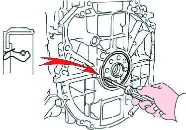
Cut off the lip of the gland with a knife. Using a cloth-wrapped screwdriver, pry out the oil seal (fig. 19).
Using sandpaper, remove the remnants of the oil seal from the edge of the rear oil seal holder.
Apply grease to the surface of the new oil seal.
Using a drift and a hammer, press in the new oil seal so that its surface does not protrude beyond the edge of the edge of the rear oil seal holder.
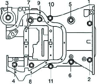
In several passes, sequentially, unscrew the eleven crankcase mounting bolts (Fig. 20).
Checking the timing chain and the sprocket of the shafts
Measure the length of fifteen links of the chain under tension with a vernier caliper.
If the chain length is fifteen links longer than the maximum, replace the chain.
Make three or more measurements on arbitrary sections of the circuit.
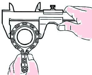
Wrap the chain around the sprocket.
Measure the diameter of the sprocket over the rollers with a vernier caliper as shown in Figure 21.
Minimum sprocket diameter:
- - camshaft - 97.3 mm;
- - crankshaft - 51.6 mm.
If the diameter is not as specified, replace sprockets with chain.
Check the tensioner shoe and timing chain guide for wear.
Maximum wear should not exceed 1 mm.
Checking the operation of the timing chain tensioner divisions
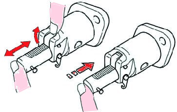
Make sure the plunger moves freely when the ratchet is raised.
Release the ratchet and make sure the plunger is locked (fig. 22).
Checking camshaft runout
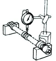
Install the camshaft on two prisms.
Place the sensitive head of the indicator on the neck.
Turn the camshaft by hand to one side and measure the runout with a dial gauge (maximum dial reading) (fig. 23).
The maximum runout tolerance is 0.03 mm.
Checking the camshaft lobe height
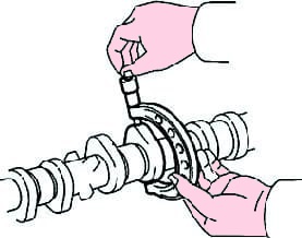
Measure the height of the camshaft lobe (fig. 24).
Standard cam contour height is 46.495–46.595 mm.
The minimum height of the cam contour is 46.385 mm.
Camshaft journal clearance (outer diameter of the camshaft journal)
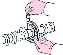
Measure the outer diameter of the camshaft journal (fig. 25).
Standard camshaft bracket inner diameter:
- No. 1.....35.971–35.985 mm;
- No. 2,3,4,5.....22.959–22.975 mm.
Installing wt sprocket (intake camshaft)
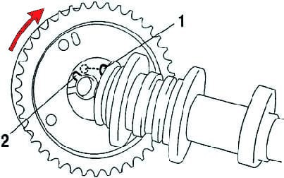
Hold the sprocket in such a position that the groove in it is slightly to the left of the camshaft locating pin (shaft side).
Install the sprocket onto the camshaft.
Press lightly on the star and rotate it counterclockwise.
Make sure there is no visible gap between the sprocket and the end of the camshaft.
Hold the shaft with a spanner and tighten the mounting bolt to 54 Nm.
Make sure the WT drive moves clockwise and locks with the locking pin in the correct position (fig. 26).


