Install the front wheel drive bearing
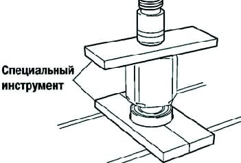
Using the special tool 09527-30010, 09527-10011 and a press, install the new front wheel drive bearing (fig. 1)
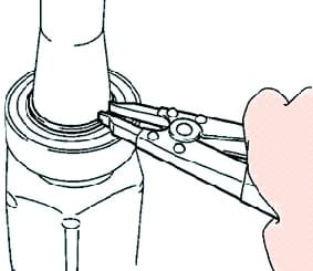
Using the circlip expander, install the new right circlip (fig. 2)
Install the front wheel drive dust cover.
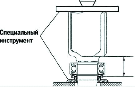
Using tool 09527-10011, 09726-40010 and a press, install the new front wheel drive dust cover.
The distance from the end of the drive shaft to the dust ring, as shown in Figure 3, must be correct. Distance: 42.1± 0.5 mm.
Install the right front wheel drive dust ring.
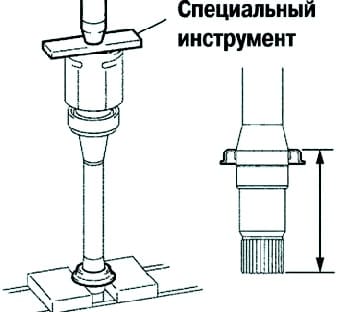
Using tool 09527-10011 and a press, install the new right front wheel drive dust ring.
The distance from the end of the drive shaft to the dust ring, as shown in Figure 4, must be correct.
Distance:
- 1AZ-FE, 2AZ-FE.....91.5 ± 0.5 mm;
- 1MZ-FE......110.5 ± 0.5 mm.
Install the left front wheel drive dust ring.
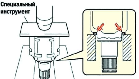
Using tool 09527-10011 and a press, install the new left front wheel drive dust ring (fig. 5).
Install the new left front wheel drive retaining ring.
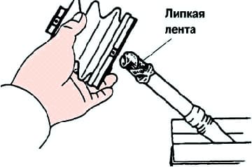
Install the protective cover of the outer hinge (fig. 6).
Before installing the boots, wrap the driveshaft spline with tape to prevent damage to the boots.
Temporarily install a new 2-clip outer joint boot on the drive shaft.
Fill the inboard joint housing and boot with grease.
Amount of lubricant:
- 1AZ-FE, 2AZ-FE.....190–200 g;
- 1MZ-FE.....205–215
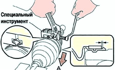
Install the collar of the protective cover of the outer hinge (Fig. 7).
Install the drive shaft in a soft vice.
Attach the 2 outer hinge protective boot straps to the boot.
Install special tool 09521-24010 on the larger collar of the outer hinge boot.
The position of the right clamp of the protective cover of the outer hinge and the left clamp of the protective cover of the outer hinge in the grooves of the cover during tightening should be as shown in Figure 3.188.
Gap: 0.8mm or more.
Tighten the screw of the special tool until the large clamp is compressed.
Do not overtighten the special tool screw.
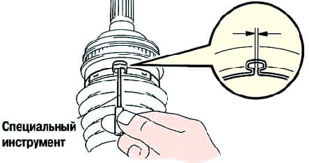
Using the special tool 09240-00020, adjust the gap of the large clamp (fig. 8).
Gap: 0.8 mm or less.
In the same way, install the small collar of the outer hinge boot.
Install the front wheel drive damper (manual transmission).
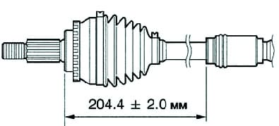
Make sure the front wheel drive damper is in the shaft groove (fig. 9).
It is necessary to maintain the distance given below. Distance: 204.4 ± 2.0 mm.
Install the right front wheel drive damper (except 1MZ-FE engine).
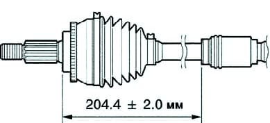
Make sure the front wheel drive damper is in the shaft groove (fig. 10).
It is necessary to maintain the distance given below. Distance: 204.4 ± 2.0 mm.
Install the inner drive joint of the front wheel.
Place the tripod with the lead-in chamfer to the outer hinge shaft.
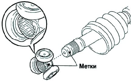
Align the mounting marks made before disassembly (Fig. 11).
Using a brass rod and a hammer, install the tripod onto the outer joint shaft.
Do not hit the rollers.
Using the circlip expander, install the new circlip onto the shaft.
Fill the inboard joint housing and boot with grease. Grease quantity: 185-195g
Install the inner joint boot onto the shaft.
Install the inner hinge boot clamp
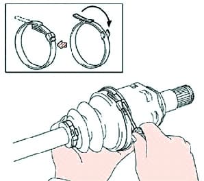
Bend the tape and secure the inner hinge boot clamps with a screwdriver (fig. 12).
Check the front wheel drive.
Make sure there is no significant play in the outer hinge.
Ensure that the inner hinge moves smoothly in the axial direction.
Make sure there is no significant radial play in the inner joint.
Check that the protective covers are not damaged.
Move the drive shaft while keeping it horizontal.
Make sure the boots are in the grooves of the shaft.
Make sure the boots are not stretched or compressed when the drive shaft is loose.
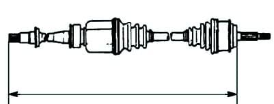
Standard drive shaft length (see below, fig. 13).
1AZ-FE, 2AZ-FE:
- left - (576.9± 2.0) mm;
- right - (896.4 ±2.0) mm.
1MZ-FE:
- left - (591.2 ±2.0) mm;
- right - (890.0 ± 2.0) mm.
Install the left front wheel drive assembly.
Coat the splines of the inner drive joint with automatic transmission fluid
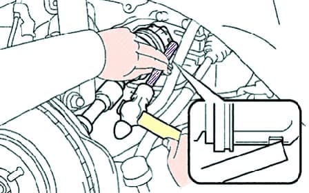
Align the shaft splines and install the front wheel drive assembly using a brass rod and hammer (fig. 14).
Install the circlip with the slit down. Be careful not to damage the oil seal.
Determine if drive is in left wheels in contact with the gear shaft, you can hear or feel when turning it.
Install the right front wheel drive assembly.
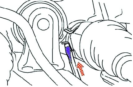
Using a screwdriver, install the driveshaft bearing circlip (fig. 15).
Install the bolt. Tightening torque: 32.4 Nm.
Be careful not to damage the oil seal.
Install the front hub.
Install the front wheel drive shank assembly into the hole in the hub.
Be careful not to damage the protective cover of the outer hinge.
Be careful not to damage the speed sensor rotor.
Install the #1 lower arm of the front suspension.
Install the lower ball joint onto the #1 front suspension arm and secure it with the bolt and nut. Tightening torque: 127 Nm.
Install the tie rod.
Install the tie rod into the steering knuckle and secure with the nut. Tightening torque: 49 Nm.
Install the new cotter pin.
If the cotter pin holes do not line up, tighten the nut an additional 60°. Install the front speed sensor.
Attach the sensor wire and front flex hose to the shock absorber with the bolt. Tightening torque: 18.8 Nm.
Install the sensor wire tie.
Mount the front speed sensor to the steering knuckle and secure with the bolt. Tightening torque: 8.0 Nm.
Be careful not to damage the speed sensor.
Make sure that dirt does not get into the installation site.
Do not twist the wire when installing the sensor.
Install the front anti-roll bar.
Install the anti-roll bar and secure it with the nut. Tightening torque: 74 Nm.
If the ball joint pin turns with the nut, use a socket wrench (6 mm) to secure the pin.
Install the front wheel hub nut.
Install the new front wheel hub nut. Tightening torque: 294 Nm.
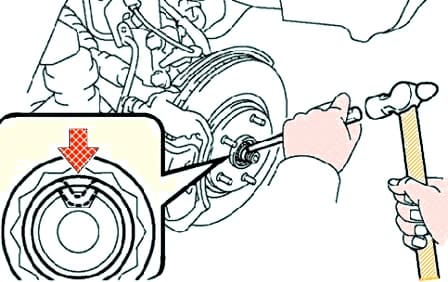
Using a chisel and hammer, roll the collar of the front wheel hub nut (fig. 16).
Install the front wheel.
Add fluid to the automatic transmission (automatic transmission).
Check the automatic transmission fluid (automatic transmission).
Add oil to the transmission (manual transmission).
Check the manual transmission oil (manual transmission).
Check and adjust the front wheel alignment.
Check ABS speed sensor signal.
For wheel drives, you can see the article Removing and installing CV joints of Toyota Camry front wheel drives


