The pressure regulator (Fig. 1) regulates the pressure in the hydraulic drive of the rear wheel brakes depending on the load on the rear axle of the car
It is included in both circuits of the brake system, and through it the brake fluid flows to both rear brake mechanisms.
There are four chambers in the regulator: "A" and "D" (fig. 1) are connected to the master cylinder, "B" to the right, and "C" to the left rear brake wheel cylinders.
In the initial position of the brake pedal, piston 2 is pressed against the pusher 20, which, under this force, is pressed against the seat 14 of valve 18.
In this case, the valve 18 is pressed from the seat and a gap "H" is formed, as well as a gap "K" between the piston head and the seal 21.
Through these gaps, chambers "A" and "D" communicate with chambers "B" and "C".
When you press the brake pedal, fluid flows through gaps "K" and "H" and chambers "B" and "C" into the wheel cylinders of the brake mechanisms.

Pressure regulator: 1 - pressure regulator body; 2 - piston; 3 - protective cap; 4, 8 - retaining rings; 5 - piston sleeve; 6 - piston spring; 7 - housing sleeve; 9, 22 - support washers; 10 - pusher sealing rings; 11 - support plate; 12 - pusher bushing spring; 13 - valve seat sealing ring; 14 - valve seat; 15 - sealing gasket; 16 - cork; 17 - valve spring; 18 - valve; 19 - pusher bushing; 20 - pusher; 21 - piston head seal; 23 - piston rod seal; 24 - plug; A, D - cameras connected to the main cylinder; B, C - chambers connected to the wheel cylinders of the rear brakes; E - connecting channel; K, M, H - gaps
As the fluid pressure increases, the force on the piston increases, tending to push it out of the housing.
When the force from the fluid pressure exceeds the force from the elastic lever, the piston begins to move out of the body, and after it the pusher 20 moves under the action of the springs 12 and 17 together with the sleeve 19 and rings 10.
In this case, the gap "M" increases, and the gaps "H" and "K" decrease.
When gap "H" is fully selected and valve 18 isolates chamber "D" from chamber "C", pusher 20, together with the parts located on it, stops moving after the piston.
Now the pressure in chamber C will vary with the pressure in chamber "B".
With a further increase in the effort on the brake pedal, the pressure in the chambers "D", "B" and "A" increases, the piston 2 continues to move out of the housing, and the sleeve 19, together with the sealing rings 10 and the plate 11, under increasing pressure in the chamber " B" is shifted towards cork 16.
At the same time, the gap "M" begins to decrease.
Due to the decrease in the volume of chamber "C", the pressure in it, and hence in the brake drive, increases and will practically be equal to the pressure in chamber "B".
When gap "K" is zero, the pressure in chamber "B", and hence chamber "C", will rise to a lesser extent than the pressure in chamber "A", due to the throttling of fluid between the piston head and seal 21.
The relationship between the pressure in chambers "B" and "A" is determined by the ratio of the difference between the areas of the head and the piston rod to the area of the head.
If the brake circuit "right front - left rear brake" fails, the sealing rings 10, bushing 19 under the pressure of the liquid in the chamber "B" will move towards the plug 16 until the plate 11 stops in the seat 14.
The pressure in the rear brake will be regulated by the regulator part, which includes piston 2 with seal 21 and bushing 7.
The operation of this part of the regulator in the event of a failure of the named circuit is similar to operation with a working system.
The nature of the change in pressure at the outlet of the regulator is the same as with a working system.
If the brake circuit "left front - right rear brake" fails, the pressure of the brake fluid pusher 20 with sleeve 19, sealing rings 10 is shifted towards the piston, pushing it out of the housing.
Gap "M" increases and gap "H" decreases.
When the valve 18 touches the seat 14, the pressure increase in chamber "C" stops, i.e. the regulator in this case works as a pressure limiter.
However, the amount of pressure achieved is sufficient for reliable operation of the rear brake.
In case 1, a hole is made, closed with a plug 24.
Leakage of liquid from under the plug when it is squeezed out indicates leakage of the rings 10.
Replacing the pressure regulator
One of the reasons for a car skidding or pulling to the side during braking may be a malfunction of the pressure regulator.
It is recommended that a defective pressure regulator be replaced as an assembly. You will need: keys "for 10", "for 13".
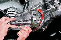
Disconnect the tip of the regulator drive lever from the lever post, as described above
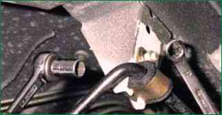
With a head of 10, unscrew the nut that secures the support sleeve cage to the bracket, holding the bolt from turning with a wrench
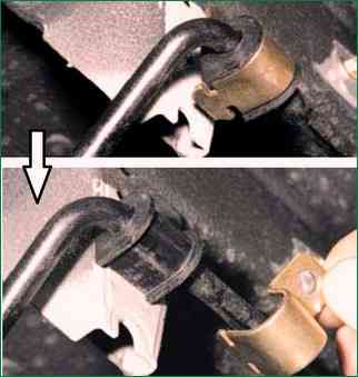
We remove the holder of the lever support sleeve from the slot of the bracket and remove the clips from the support sleeve
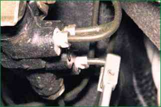
With a special wrench for brake pipes, unscrew the fittings of the three brake pipes located on the side of the regulator
Unscrew the tube fitting located in front
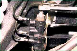
Remove the tubes from the pressure regulator
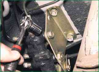
With a 13 head, unscrew the two bolts securing the regulator housing to the bracket
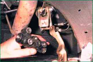
Remove the regulator and plate
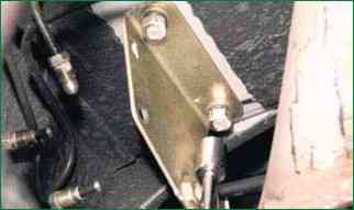
To remove the pressure regulator bracket with a 13 head with an extension, unscrew the two nuts securing the bracket to the body
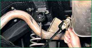
Remove the bracket assembly with the regulator drive, bringing it out from behind the muffler pipe
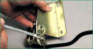
Using an 8 spanner wrench, unscrew the bolt securing the lever base plate
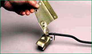
Sliding the plate, remove the regulator mounting bracket
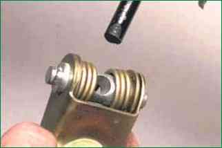
Remove the lever from the hole in the axle
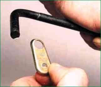
Remove the base plate from the lever
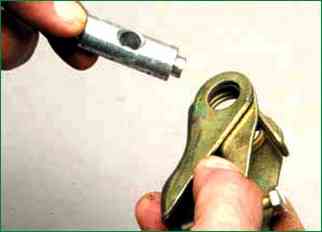
Remove the lever axis
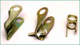
Disconnect the levers of the piston, the regulator drive and the lever spring
It is not necessary to unscrew the adjusting bolt from the regulator drive lever
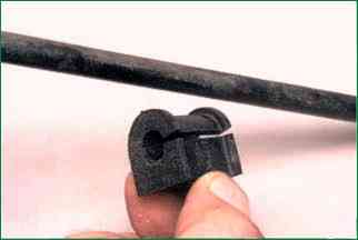
Opening the rubber support sleeve, remove it from the lever
Install the pressure regulator and all parts in the reverse order.
We pump the brake hydraulic drive (described in the article - Replacing the Niva Chevrolet brake fluid) and adjust the drive as described above.
Apply a thin layer of graphite grease to the regulator shaft and the protruding part of the piston.
We put a little grease in the protective cap and put it in place.


