On VAZ-2123 vehicles, an ignition switch of type 2123–3704005 is used with an anti-theft locking device, a lock against restarting the starter without first turning off the ignition, and an ignition key transponder communication coil with an automobile anti-theft system
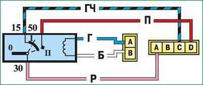
At the ignition switch, they check the correct closure of the contacts at various key positions (Table 1), the operation of the anti-theft device and the presence of communication with the car anti-theft system.
The voltage from the battery and the generator is supplied to terminal "30" (Fig. 1).
Relay K6 is installed in the mounting block to unload the contacts of the ignition switch.
The locking rod of the anti-theft device should extend when the key is turned to position 0 (off) and removed from the lock.
The locking rod must retract when the key is turned from position 0 (off) to position I (ignition).
The key must only be removed from the lock in position 0.
The locking device against restarting the starter must not allow the key to be turned again from position I (ignition) to position II (starter).
Such a turn should be possible only after the key has been previously returned to position 0 (off).
Removing and disassembling the ignition switch
We remove the ignition lock to replace or to replace the contact group of the lock, as well as when replacing the APS coil
Disconnect the negative battery terminal
Remove the steering column switch (described in the article - removing the steering column switch)
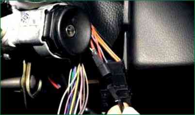
Disconnect the wire block of the anti-theft coil from the block of the wiring harness
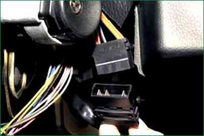
Disconnect the wire block of the contact part of the ignition switch from the block of the wiring harness
All work is shown for clarity on the removed steering column
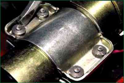
With a chisel, loosen the four bolts (with cut heads) securing the ignition switch
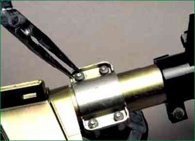
We unscrew the bolts with pliers
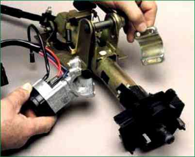
Remove the bracket and ignition switch
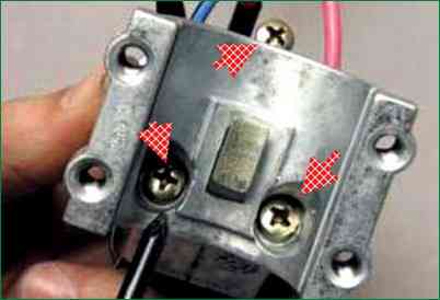
Use a Phillips screwdriver to unscrew the three screws
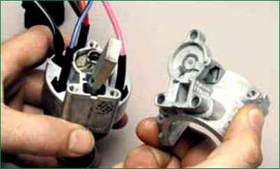
And remove the ignition switch bracket
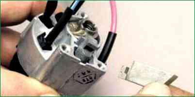
Remove the locking rod of the anti-theft device
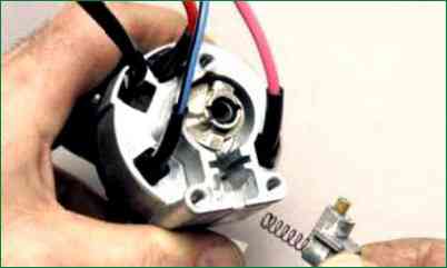
Povora we remove the key in the ignition switch and remove the drive of the locking device

Remove the rod spring from the drive
Remove the stopper with the spring
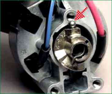
We push the cylinder out of the switch body and remove the locking ball
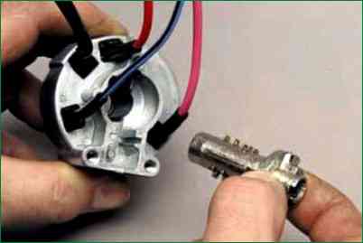
Remove the cylinder from the switch body
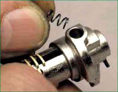
Remove the locking ball spring from the hole in the cylinder
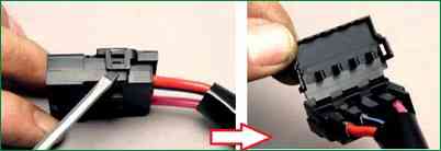
Pry off the latches of the wire block cover with a screwdriver
Opening the wire block cover
In order not to confuse the wires when installing in the block, we mark the location of the wires relative to the block
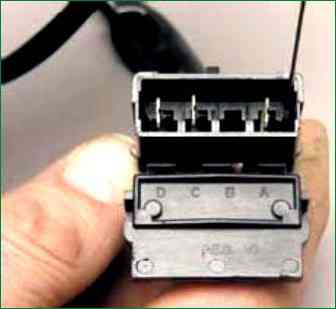
With a thin awl or needle, we bend the locking antennae of the wire tips
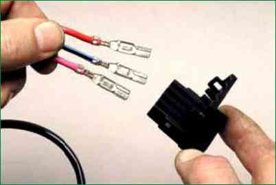
Remove the wire ends from the block
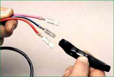
Remove the insulating tube from the wires
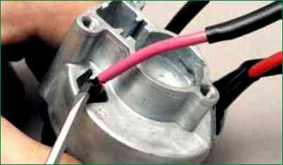
We squeeze three plastic latches with a screwdriver and remove the contact group from the case
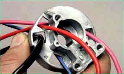
We bring the wires through the holes in the case
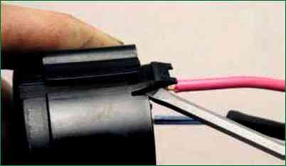
Pry off with a screwdriver and disengage three plastic latches
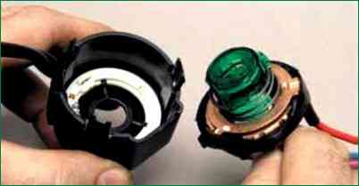
And disconnect the contact group
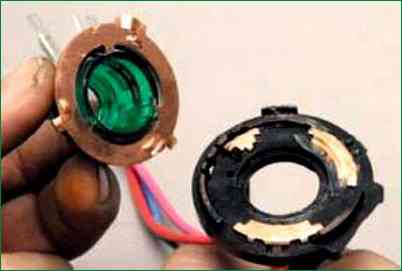
Remove the moving part of the contact group

Click on the moving contact and turn it counterclockwise
Remove the moving contact from the housing
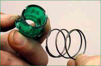
Remove the contact spring

Pry off the APS coil with a screwdriver
Remove the APS coil
We assemble and install the ignition switch in the reverse order
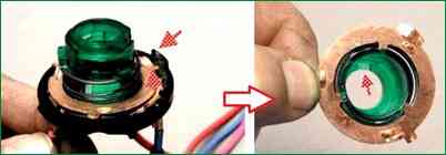
We install the moving part of the contact group so that the wide protrusion of the movable contact is located opposite the protrusion on the cover with the fixed contact
And the protrusion on the lock cylinder should enter the recess on the body of the moving part of the contact group.
Switched circuits at different key positions
In key position (I) - Circuits turn on:
- - engine management system;
- - generator excitation;
- - headlights;
- - turn signal;
- - control devices;
- - cleaners and washers of wind and rear windows;
- - window lift motors for front doors
Live contacts 30-50
In position (II) (starter), the starter circuits are switched on
Live contacts 30-50


