Adjusting the Mazda 3 automatic transmission range switch
Disconnect the cable from the negative battery terminal.
Remove the nut and disconnect the transmission control cable (fig. 1).
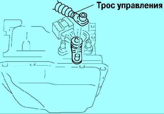
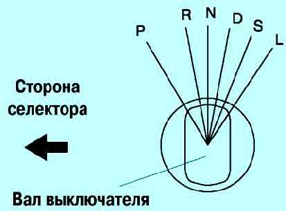
Set the start inhibit switch shaft to position (N) as shown in figure 2.
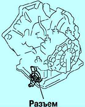
Disconnect the start inhibit switch connector (fig. 3)
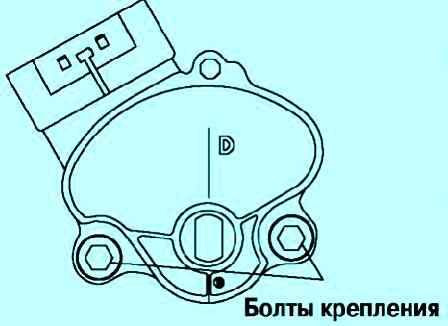
Loosen the bolts securing the start inhibit switch (fig. 4)
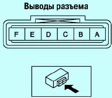
Connect an ohmmeter to terminals (B) and (C) of the start inhibit switch connector (fig. 5)
Turn the start inhibit switch to determine the position at which conduction occurs between the terminals of the connector.
Nominal ohmmeter reading: 750 ohm.
Tighten the start inhibit switch mounting bolts. Tightening torque: 8–11 Nm.
Check that the position of the selector matches the position of the start inhibit switch.
Connect the start inhibit switch connector.
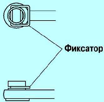
Install the transmission control cable retainer as shown in Figure 6.
Tighten the transmission control cable nut and adjust its position.
Install the retainer and the transmission control cable.
Connect the negative battery terminal.
Automatic transmission mode sensor - check and replacement
A special sensor is installed on the case of the automatic transmission, which informs the control unit about the selected operating mode, as well as turning on the reverse lights and breaking the circuit of the starter solenoid relay in certain modes.
If the reversing lights or the starter do not turn on (in positions P and N), you need to perform a sensor test
Before you start, you need to make sure that the selector cable is adjusted correctly, article - Replacing the selector lever
Running
Install the car on a lift or overpass
Remove the mudguard of the engine compartment
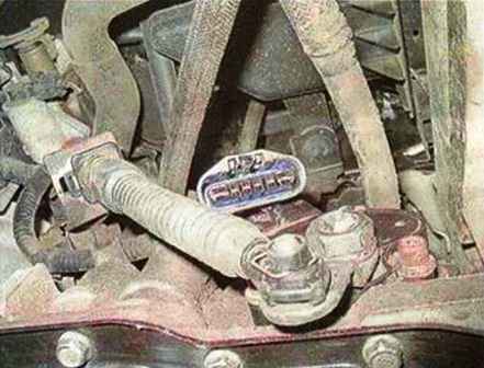
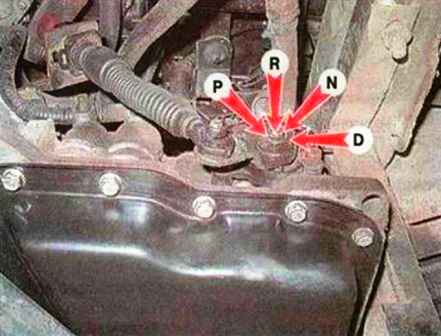
Press the latch and disconnect the wiring harness block from the sensor
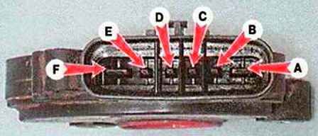
With a tester in ohmmeter mode, we check, at various positions of the sensor lever, the closure of the corresponding contacts (shown on the removed sensor)
Contact closure diagram
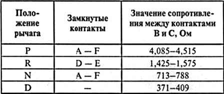
If any contacts do not close or do not close according to the table, you can try to adjust the sensor
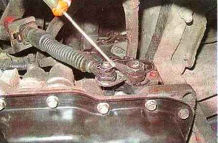
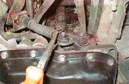
To do this, pry off the cable retainer with a thin screwdriver and remove it from the axis
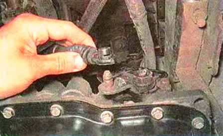
Disconnect the selector cable from the axis
Lower the lever all the way down (to position (P)), and then raise it two clicks up (to position (N))
Re-measure the resistance between contacts (B) and (C)
If the resistance is between 713-788 ohms, the sensor is defective and needs to be replaced
If the resistance is out of the specified range, use a 5 mm hex wrench to loosen the sensor mounting bolts
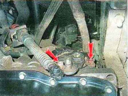
And, slightly turning the sensor body, set the resistance between the contacts (B) and (C), equal to 750 Ohm
Tighten the sensor mounting bolts and repeat the check for contact closure
If the specified resistance value cannot be set or any contacts still do not close, replace the sensor
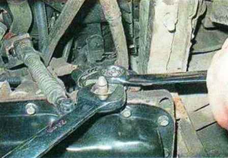
Using a 22 wrench, unscrew the lever fastening nut, holding the lever from turning with a 24 wrench
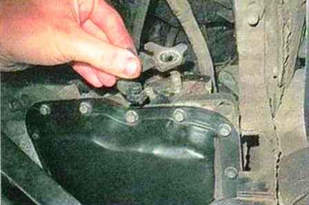
Remove the washer and lever
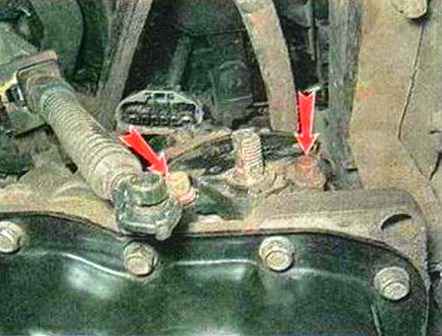
Unscrew the mounting bolts with a 5 hexagon wrench and remove the sensor
Install parts in reverse order
After installation, we adjust the sensor and selector cable


