Loosen the camshaft sprocket mounting bolts (camshaft timing mechanism mounting bolt) as shown in Figure 2.
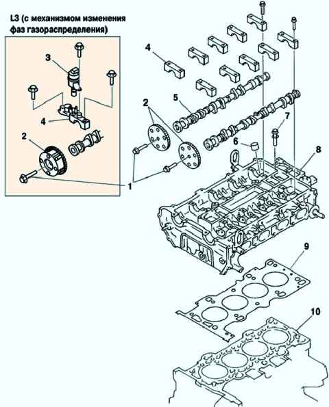
Remove the camshaft sprockets.
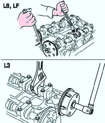
Variable valve timing actuator (L3 with variable valve timing mechanism).
Remove the oil control valve (OCV) (L3 with variable valve timing).
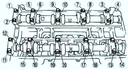
Remove the camshaft bearing caps by loosening the mounting bolts in three steps in the order shown in Figure 3.
Before removing the camshaft bearing caps, check the camshaft end play and the clearances in the camshaft bearings.
Camshaft bearing caps are numbered to ensure correct reassembly.
Once removed, keep the covers together with the cylinder head from which they were removed. Do not mix caps.
Remove the camshafts.
Remove the valve lifters.
Valve lifters are numbered to ensure correct reassembly.
After removal, keep the valve lifters together with the cylinder head from which they were removed. Do not mix valve lifters.
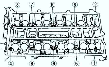
Loosen the cylinder head bolts in two or three steps in the order shown in Figure 4.
Installing the cylinder head
Install the cylinder head.
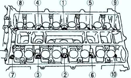
Tighten the cylinder head bolts in the order shown in Figure 5 in six steps.
- 1.Tighten to 5.0 Nm
- 2.Tighten to 13-17 Nm
- 3.Tighten to 44-46 Nm
- 4.Tighten 88-92°.
- 5.Tighten 88-92°.
- 6.Tighten completely.
Installing camshafts
Install the camshafts with the #1 cylinder piston at TDC on the compression stroke.
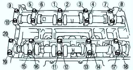
Tighten the camshaft bearing cap bolts in two steps (fig. 6).
- 1.Tighten to 5.0 - 9.0 Nm
- 2.Tighten to 14.0-17.0 Nm
Assembly instructions for camshaft sprocket, variable valve timing actuator (L3 with variable valve timing).
Camshaft sprocket bolt or variable valve timing actuator (L3 with variable valve timing mechanism) is temporarily screwed in by hand until the timing chain is installed.
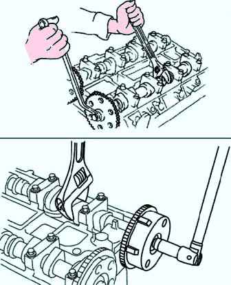
Camshaft sprocket or timing actuator connecting bolt valve timing (L3 with a mechanism for changing the valve timing) after installing the drive chain of the gas distribution mechanism is installed on the adhesive (Fig. 7). Tightening torque: 69–75 Nm.


