An integrated sensor is installed on the left side of the parking brake lever (left-hand drive models) or on the right side of the parking brake lever (right-hand drive models) and detects the vehicle's yaw rate (vehicle's cornering speed) and longitudinal acceleration
The sensor transmits a signal to the DSC HU/CM system.
The output voltage of the combined sensor is 2.5V when the vehicle is stationary) varies according to the yaw rate and the amount of longitudinal acceleration.
Yaw rate is determined when the sensor detects a Coriolis force proportional to the rotation speed.
The magnitude of the longitudinal acceleration is determined when the sensor detects an inertial force proportional to the longitudinal acceleration acting on the silicon sensing element.
Coriolis force. When an object on a rotating disk moves towards its center, a force is generated that is at right angles to the object's path.
This causes the object's direction of travel to remain the same relative to the starting point, and the object does not reach the center.
This force that deviates the object from the center is called the Coriolis force, and the actual movement of the object is rectilinear.
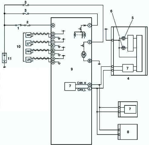
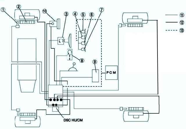
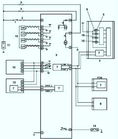
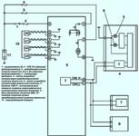
Fig. Fig. 1. Wiring diagram of the ABS/TCS system of the brake circuit of a Mazda 3 car: 1 – switch IG; 2 - SUS 10 a (fuse); 3 - anti-lock braking system 20 a and 30 a (fuses); 4 – a combination of devices; 5 – a lamp of the alarm system of antiblocking system of brakes; 6 – a lamp of the alarm system of brake system; 7 – CAN driver; 8 - the actuator of the automatic speed control system; 9 - ABS system control unit; 10 - wheel speed sensors of the anti-lock braking system; 11 - BatteryFig. Fig. 2. Scheme of operation of the DSC HU/CM system of the Mazda 3 PCM unit: 1 – wheel speed sensor; 2 – sensor rotor; 3 – rotation angle sensor; 4 – a control lamp of the DSC system; 5 – a control lamp of shutdown of the DSC system; 6 - alarm lamp; 7 – a lamp of the alarm system of antiblocking system; 8 - combined sensor; 9 - audio unit, wiper and washer, automatic speed control actuator, washer switch, car navigation and leveling control unit; 10 - master cylinder; 11 - electrical signal; 12 - brake fluid; 13 - CAN lineFig. Fig. 3. Wiring diagram of the DSC system of the brake circuit of the Mazda 3 car: 1 - switch IG; 2 - SUS 10 a (fuse); 3 - anti-lock braking system 20 a and 30 a (fuses); 4 – a combination of devices; 5 – a lamp of the alarm system of antiblocking system of brakes; 6 – a lamp of the alarm system of brake system; 7 – CAN driver; 8 - the actuator of the automatic speed control system; 9 - control unit of the DSC system; 10 - speed sensors of the anti-lock braking system; 11 - battery; 12 - steering wheel angle sensor; 13 – CAN controller sensor; 14 - DSC system switch; 15 - DSC shutdown lamp; 16 - DSC warning light

")
")
")
")
")
")