")
")
")
")
")
")
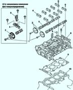
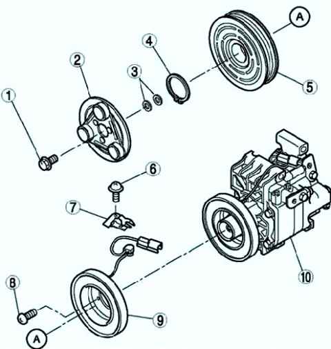
Disassembling and assembling the compressor overrunning clutch
Disassemble in the order shown in Figure 1.
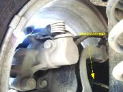
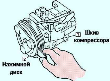
Removing the freewheel bolt
When removing and installing the bolt, hold the pressure plate as shown in Figure 2.
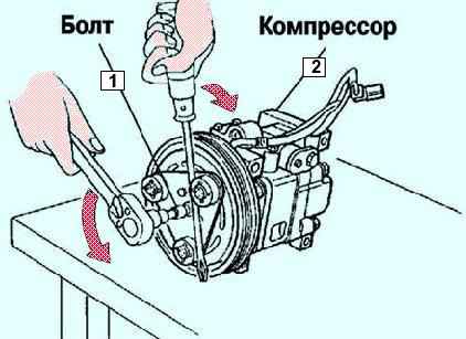
When installing a new air conditioning compressor, replace the bolt.
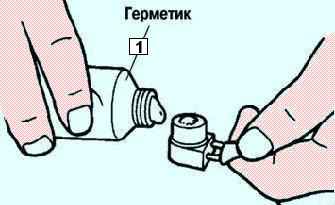
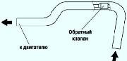
After removing the stator and thermal protector, completely remove the sealant from the air conditioning compressor side (fig. 3).
Before installing, apply approximately 1g of silicone sealant (KE-347W sealant or similar) to the contact surface of the heat protector, then carefully install it on the air conditioning compressor without leaving any gaps.
When installing a new stator and thermal protector, replace the screw.
When mounting a new stator and thermal protector, replace the clamp.
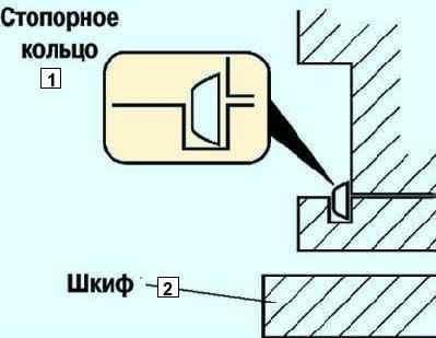
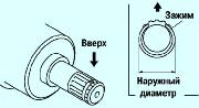
When installing a new pressure plate, air conditioning compressor pulley, stator or compressor housing, replace the circlip (fig. 4).
Freewheel adjustment
Measure the circumferential clearance between the pressure plate and the air conditioning compressor pulley using a thickness gauge (fig. 5).
Make sure the clearance is correct.
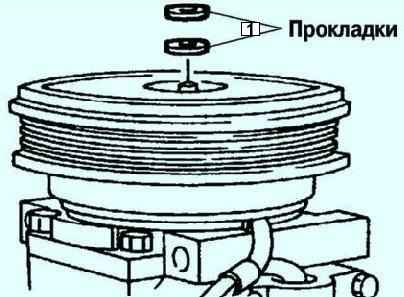
If this is not the case, remove the pressure plate and adjust the gap by selecting a 0.2-0.5 mm shim or several shims (Fig. 6).
Checking the A/C compressor freewheel
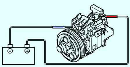
Apply voltage from the positive battery terminal to terminal (A) of the magnetic coupling, and connect the air conditioning compressor housing to body ground (Fig. 7).
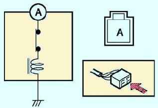
If the test shows no continuity, replace the stator and thermal protector (fig. 8).