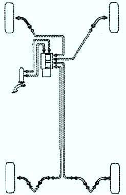
The car is equipped with two diagonal brake circuits
One circuit uses the front right and rear left wheels, the second circuit uses the front left and rear right wheels
When only one of the circuits is working, you have to press the brake pedal harder to achieve the braking of the car.
This increases the pedal travel and lengthens the stopping distance.
When you press the brake pedal, the pusher presses on the two pistons of the master brake cylinder, which through the brake booster form pressure in the system.
The brake master cylinder cannot be repaired. If it fails, it must be replaced as an assembly.
The pistons transmit the pedal force via a hydraulic line to the brake calipers.
The caliper pushes the piston of the wheel cylinder, which, in turn, presses the lining against the brake disc.
When the pedal is released, the piston returns to its original position and the pads move away from the disc.
The distance between the pads and the disc leaves 1 mm, this is enough for the disc to rotate freely.
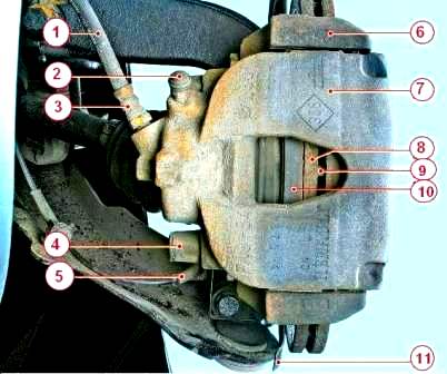
Front wheel brake: 1 — flexible brake hose; 2 - protective cap of the air release valve; 3 — the union of a flexible brake hose; 4 - mud-proof cover of the lower guide pin of the brake mechanism; 5 - wheel speed sensor; 6 - guide pads; 7 - movable bracket; 8 - brake disc; 9 - jumper air channels for cooling the brake disc; 10 - internal brake shoe; 11 - brake shield
The brake mechanisms of the front wheels (Fig. 2) are disc, with automatic adjustment of the gap between the pads and the disc 8, with a movable caliper 7.
A single-piston working brake cylinder is mounted on the movable bracket.
Shoe guide 6 is bolted to the steering knuckle.
The movable bracket is attached with guide pins installed in the holes of the shoe guide.
The guide pins are lubricated with grease and protected by dirt covers.
A piston with a sealing ring is installed in the cavity of the wheel cylinder.
Due to the elasticity of this ring, an optimal clearance is maintained between the pads and the ventilated disc, the surface of which is protected by the brake shield.
When braking, the piston, under the action of fluid pressure, presses the inner pad against the disc, the reaction force moves the movable bracket on the fingers and the outer pad is also pressed against the disc, while the pressing force of the pads is the same.
When releasing the piston, due to the elasticity of the sealing ring, it is removed from the pad, resulting in a small gap between the pads and the disc.
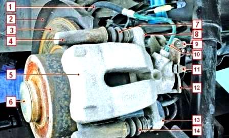
Rear wheel brake: 1 — flexible brake hose; 2 - brake shield; 3 - brake disc; 4 - guide pads; 5 - movable bracket; 6 - protective cap of the wheel hub nut; 7 - mudguard of the upper guide pin; 8 — a bolt of fastening of the top directing finger; 9 — a tip of a cable of a drive of a parking brake; 10 — the pipeline of the brake mechanism; 11 - protective cap of the air release valve; 12 - expanding lever of the parking brake drive; 13 — a bolt of fastening of the bottom directing finger; 14 - dirt cover of the lower guide pin
Brake mechanisms of the rear wheels are disc, with automatic adjustment
The brake pads are actuated by a single hydraulic working cylinder.
The optimal clearance between disc 3 (Fig. 3) and the pads is maintained according to the same principle as for the front wheel brakes.
The tip 9 of the parking brake cable is connected to the expansion lever 12 mounted on the movable bracket 5.
The parking brake lever, fixed between the front seats on the floor tunnel, is equipped with a cable tension adjustment mechanism and is connected to the equalizer by a front cable.
The front ends of the cables are connected to the equalizer of the tension mechanism.
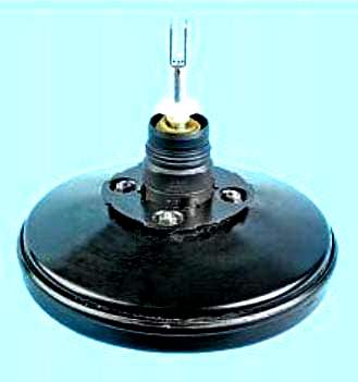
Vacuum brake booster reduces the force on the brake pedal, making driving easier.
The vacuum amplifier uses a diaphragm, on both sides of which a vacuum is created during normal operation.
During braking, air is supplied from one side of the diaphragm, forming atmospheric pressure.
Due to the pressure difference transmitted through the diaphragm, the pusher moves towards rarefaction (vacuum), providing an auxiliary force for braking.
When the brake pedal is released, air is pumped out of the amplifier cavity through the control valve, creating a vacuum.
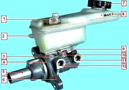
Brake master cylinder with reservoir: 1 — brake fluid level sensor connector; 2 - fluid output fitting to the main cylinder of the clutch release drive; 3.10 - connecting sleeves; 4 - sealing ring; 5 - piston pusher; 6 — the main brake cylinder; 7 - tank cap; 8 - reservoir of the main brake cylinder; 9 — a pin of fastening of a tank to the main brake cylinder; 11 - hole of the second circuit; 12 - hole of the first circuit
Brake master cylinder is used on dual-circuit brake systems.
The front right and rear left brakes are actuated by the primary piston, while the front left and rear right are actuated by the secondary piston.
The brake master cylinder combines the functions of a standard dual brake master cylinder plus a low brake fluid indicator and brake pressure regulator.
The pressure regulator limits the output pressure to the rear brakes after the pressure reaches the limit value in the master brake cylinder.
The regulator is used when less force is needed on the rear brakes to achieve optimal braking.
The brake fluid level sensor located in the brake fluid reservoir turns on the BRAKE warning light when the fluid level is low.
As soon as the brake fluid reaches the correct level, BRAKE goes out.
The anti-lock braking system (ABS) consists of wheel speed sensors, a brake pedal switch, a hydro-electronic control module (HECU) and an indicator in the instrument cluster.
The anti-lock braking system is also equipped with a self-diagnosis system that detects malfunctions of system components.
ABS is used to regulate the pressure in the brake mechanisms of all wheels when braking in difficult road conditions, preventing the wheels from blocking.
The ABS system provides the following benefits:
- — avoiding obstacles with a higher degree of safety, including during emergency braking;
- — reduction of the braking distance during emergency braking while maintaining roadholding and vehicle controllability, including when cornering.
In the event of a system failure, diagnostics and maintenance functions are provided in case of system failures.
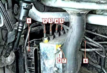
ABS hydroelectronic module: 1 — hydroelectronic module connector; 2 - pipeline of the working cylinder of the brake mechanism of the right front wheel; 3 - pipeline of the working cylinder of the brake mechanism of the left rear wheel; 4 - pipeline of the working cylinder of the brake mechanism of the right rear wheel; 5 - pipeline of the working brake cylinder of the mechanism of the left front wheel; 6.7 - pipelines of the main brake cylinder; 8 - pump
The hydro-electronic control module (fig. 6) receives information about the vehicle speed, direction of travel and road conditions from the wheel speed sensors, the steering angle sensor, the throttle position sensor.
After the ignition is switched on, the control unit supplies voltage to the wheel speed sensors.
Sensors use the Hall effect and generate an output signal in the form of rectangular pulses.
The signal changes in proportion to the rotational speed of the sensor's pulse ring mounted on the outer joint housing of the wheel drive.
Based on this information, the control unit determines the optimal wheel braking mode.
Connections and pipelines of the brake system
Connection of piping between brake master cylinder, brake calipers and hydraulic block is carried out by means of threaded fittings with metric thread.

Brake fluid
Brake technology, and in particular disc brakes (hollow pistons that transmit little heat, a small amount of fluid in the cylinder, floating calipers that eliminate the need for a relatively large supply of fluid in the least cooled part of the wheel), allows you to minimize the risk of " vapor lock" even in the case of frequent and prolonged use of the brakes (in the mountains).
However, the performance of the brake fluid deteriorates somewhat during the first months of operation due to slight absorption of moisture.
This necessitates a brake fluid change.
Brake fluid change interval
As the brake pads wear, the level of brake fluid in the reservoir gradually decreases.
There is no need to compensate for this drop: the level will be restored at the next brake pad change.
At the same time, the level should not be allowed to fall below the minimum allowable mark.
Mixing two incompatible brake fluids in a hydraulic actuator can lead to significant fluid leakage, mainly due to deformation of the seals.
To prevent this, use only brake fluids that have been tested and approved by the technical department and comply with SAE J 1703-DOT4.
For optimal operating conditions of the braking system of Renault cars, it is recommended to use low viscosity brake fluids at low temperatures (no more than 750 mm / s at 40 ° C).
Possible brake problems and solutions
Increased brake pedal stroke
Brake fluid leak from caliper slave cylinders - Replace caliper
Air in the brake system - Bleed the system
Hoses or lines of the hydraulic brake drive are damaged - Replace the hoses or lines, bleed the system
Insufficient braking performance
Oiling the brake pads - Replace the brake pads
Jamming of the pistons of the working cylinder - Check and if necessary replace the sliding bracket
Complete wear of the brake pads - Replace the brake pads
Brake overheating - Stop immediately and let the brakes cool down
Using poor quality pads - Use original pads
Violation of the tightness of one of the circuits (accompanied by the failure of the brake pedal) - Find and eliminate the cause of the leakage, bleed the system
ABS malfunction - Check ABS system
Incomplete release of all wheels
No free play on brake pedal - Replace vacuum booster tappet
ABS Malfunction - Check ABS
Braking of one wheel when the pedal is released
Piston sticking in the working cylinder due to contamination or corrosion of the body - Replace the sliding bracket
Jamming master cylinder pistons - Check and if necessary replace the sliding bracket
Violation of the position of the brake mechanism relative to the brake disc when the mounting bolts are loosened - Tighten the mounting bolts, if necessary, replace damaged parts
Incorrect parking brake adjustment - Adjust the parking brake
ABS malfunction - Check ABS system
Sliding or pulling the car to the side when braking
Jamming of the piston of the working cylinder - Check and eliminate the jamming of the piston in the cylinder
Clogging of any pipeline due to a dent or blockage - Replace the pipeline
Dirty or oily discs and brake pads - Clean brake parts
One of the brake circuits does not work (accompanied by a decrease in braking efficiency) - Replace damaged parts and bleed the system. If this does not fix the problem, check the ABS
Increased effort on the brake pedal when braking
Vacuum booster defective - Replace booster
The hose connecting the vacuum booster and the engine reservoir is damaged or its fastening is loose - Replace the vacuum hose
Squeak or vibration of the brakes
Oiling the friction linings - Replace the brake pads. Eliminate the causes of fluid or grease getting on the brake pads
Brake pad wear - Replace brake pads
Excessive runout or uneven wear (felt by vibration of the brake pedal) of the brake disc - Replace the disc if the thickness is less than tolerance


