We replace the coolant pump in case of failure of the bearing or self-locking stuffing box
We drain the coolant from the engine (described in the article - Replacing the Niva Chevrolet coolant)
Remove the auxiliary drive belt, described in the article replacing the drive belt of the water pump and Niva Chevrolet generator
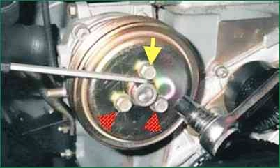
With a 13 head, we loosen the tightening of the three bolts securing the coolant pump pulley
We hold the pulley from turning with a flat screwdriver, alternately inserting it between the head of each mounting bolt and the shoulder of the pulley hub.
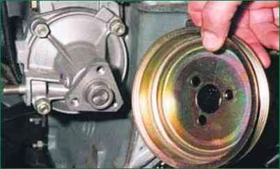
Remove the bolts and remove the pulley
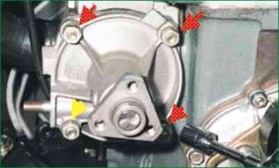
With a 13 head, unscrew the four nuts securing the coolant pump cover
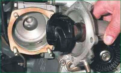
Remove the pump cover assembly with the impeller and bearing
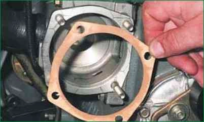
The junction of the cover and the pump housing is sealed with a gasket
Install the pump cover in reverse order
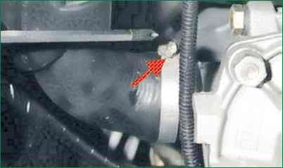
To remove the coolant pump assembly with a screwdriver, loosen the clamp securing the inlet hose to the pump housing
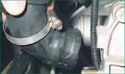
Remove the hose from the body pipe
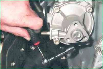
With a 13 head with an extension, unscrew the two bolts of the lower fastening of the pump housing to the cylinder block
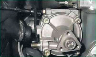
We unscrew one bolt of the upper fastening
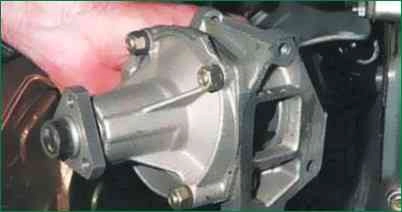
Remove the coolant pump assembly
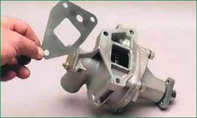
The joint between the coolant pump housing and the cylinder block is sealed with a gasket
We install the pump in the reverse order
Disassembly of the coolant pump
To disassemble the pump:
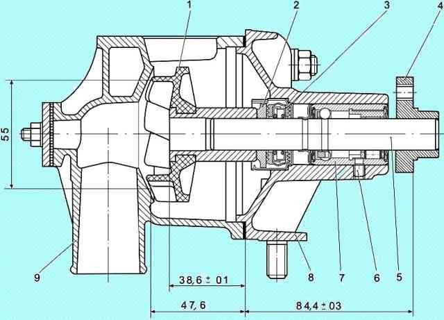
- disconnect the casing 9 (Fig. 12) of the pump from the cover 8;
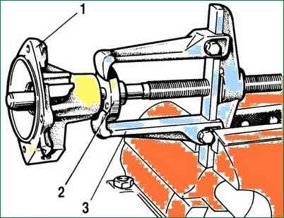
- - install the universal puller 3 (Fig. 13) and press the hub of the fan pulley;
- - unscrew the locking screw 6 (fig. 12), press out the bearing 7 together with the impeller 1 towards the stuffing box;
- - install a universal puller, compress the impeller and remove the oil seal.
Control
Check the axial clearance in the bearing. This operation must be performed if significant pump noise has been noted.
The gap must not exceed 0.13 mm with a load of 49 N (5 kgf). With a larger clearance, replace the bearing assembly with the roller with new ones.
It is recommended to replace the pump seal and the gasket between the pump and the cylinder block with new ones during repairs.
Inspect the pump housing and cover, no deformation or cracks are allowed.
Pump Assembly
Assemble in the following order:
- - using mandrel 41.7853-4028, press the stuffing box into the housing cover;
- - press a new bearing with a roller into the cover, aligning the seat of the lock screw with the hole in the housing cover, wrap and caulk the hole of the lock screw;
- - using a technological rod with a diameter of 25 mm and a length of 20 mm, press the hub of the fan pulley onto the roller;
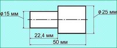
- - using a mandrel (Fig. 14) press the impeller onto the roller;
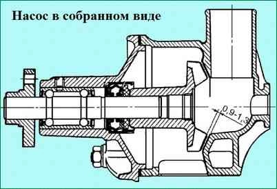
- - check the size 0.9-1.3 mm (Fig. 15);
- - install the gasket and connect the cover to the body (socket key 13);


