Checking and adjusting the thermal clearances of the 1mz-fe engine valves
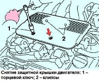
Using a 5mm socket wrench, unscrew the two nuts and remove the motor protection cover
Using an 8mm socket wrench, remove the intake manifold top (fig. 1).
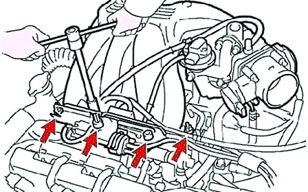
Remove the ignition coils.
Remove the spark plugs.
Remove the cylinder head covers.
Disconnect the high voltage wires from the spark plugs, holding them only by the rubber lugs
Removing the cylinder head cover
Disconnect the two crankcase ventilation hoses from the cylinder head cover.
Disconnect the two harness guard clips from the #2 timing belt cover mounting bolts.
Remove the four nuts, remove the spark plug tube seal.
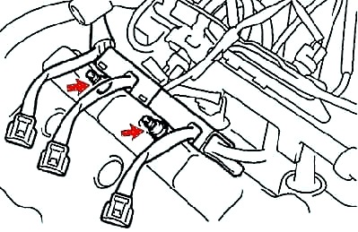
Remove the two nuts at the front of the engine and disconnect the wiring protection from the front cylinder head (fig. 2).
Remove the cylinder head cover and gasket.
In order to minimize oil leakage, arrange the spark plug tube seals in the removal order to reinstall them correctly.
Setting the piston of the first cylinder to TDC of the compression stroke
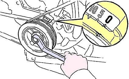
Turning the crankshaft pulley, align the notch on the pulley with the installation marking "0" on the timing belt cover No. 1 (Fig. 3).
Checking valve clearances
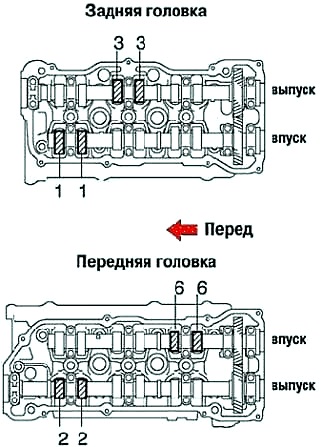
Check the thermal gaps in the valves shown in Figure 4.
Using a feeler gauge, measure the clearance between the cam and the valve lifter. Record the results.
These will be used later when determining the thickness of the shim.
Thermal clearance in the valves (on a cold engine):
- inlet - 0.15–0.25 mm;
- graduation - 0.25–0.35 mm.
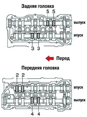
Rotate the crankshaft 240° (2/3 turn) and check the clearance in the valves shown in figure 5.
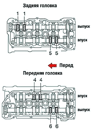
Rotate the crankshaft again 240° (2/3 turn) and check the clearance in the valves shown in figure 6.
Adjustment of thermal clearances in valves
If necessary, adjust the valve clearance.
To do this, remove the shim.
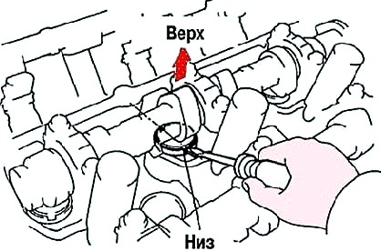
Rotate the camshaft so that the top of the cam is pointing up.
Position the valve lifter as shown in Figure 7.
Use special tool 09248-05410 (A) and 09248-05420 (B).
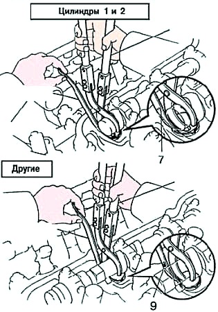
Using the special tool (A), press the tappet and place the special tool (B) between the camshaft and the tappet.
Remove the special tool (A).
Insert the special tool (B) at a slight angle and make sure that the markings on the special tool are positioned as shown in figure 8.
If the special tool (B) is inserted too deep, the shim may jam it.
To prevent this, insert it from the side of the intake valves at a slight angle.
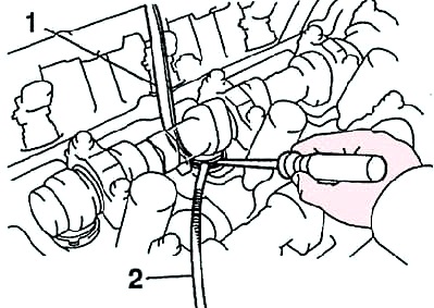
Remove the shim using a small screwdriver and a magnetic bar (fig. 9).
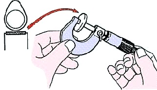
Using a micrometer, measure the thickness of the removed shim and determine the size of the new shim (fig. 10).
Calculate the thickness of the new shim so that the clearance in the valves is within the specified values:
- thickness of the removed shim - T;
- measured valve clearance - A;
- The thickness of the new shim is N.
1MZ-FE:
- inlet - N \u003d T + (A - 0.2 mm);
- graduation - N \u003d T + (A - 0.3 mm).
Choose a new shim with a thickness as close as possible to the calculated value.
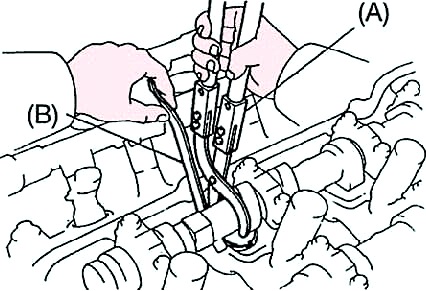
Install the new shim into the pushrod with the stamped number on the shim facing down.
Using the special tool (A), press the pusher and remove the special tool (B) (fig. 11).
Check the valve clearance again.
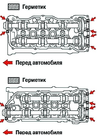
Remove the old sealing material and apply sealant to the cylinder head, in the places shown in figure 12.
Install the cylinder head covers.
Install and tighten the spark plugs.
Install the ignition coils.
Install upper intake manifold assembly.
Install the protective cover.


