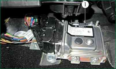
The engine management system controller is installed under the instrument panel on the bulkhead in front of the passenger
You will need: a 10 wrench (preferably a socket), a screwdriver.
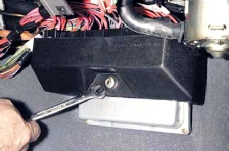
Remove the cover of the fuse and relay box (see "Replacing the fuses of the Niva Chevrolet engine management system").
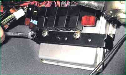
We unscrew the three nuts securing the relay and fuse box
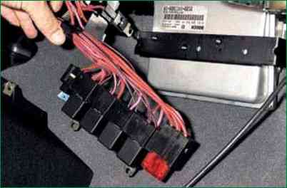
Disconnect the assembly from the bracket
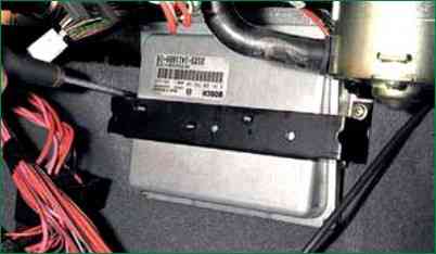
Use a Phillips screwdriver to unscrew the two screws securing the bracket
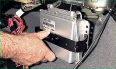
Remove the controller together with the bracket
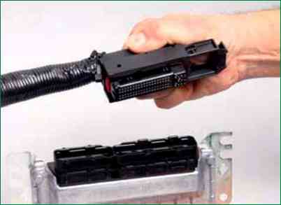
Pull out the harness block retainer and disconnect it from the controller
Install the controller and fuse/relay box in the reverse order of removal
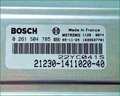
Pay attention to the drawing designation of the controller (2123–1411020–40).
Purchase a new controller with the same designation, regardless of what type of product is indicated on it.
The controller of a car manufactured since 2015 under Euro-5 is also installed in the area of the passenger's legs and is attached to the front panel
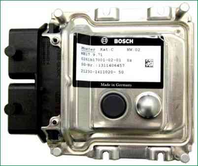
The controller controls actuators such as fuel injectors, motorized throttle, ignition coil, oxygen sensor heater, canister purge valve, and various relays.
The controller controls the on and off of the main relay (ignition relay), through which the supply voltage from the battery is supplied to the elements of the system (except for the electric fuel pump, electric fan, control unit and APS status indicator).
The controller turns on the main relay when the ignition is turned on.
When the ignition is turned off, the controller delays turning off the main relay for the time necessary to prepare for the next turn on (completion of calculations, setting the throttle to the position before starting the engine).
When the ignition is turned on, the controller, in addition to performing the functions mentioned above, exchanges information with the APS (if the immobilization function is enabled)
If the exchange determines that access to the vehicle is allowed, then the controller continues to perform engine control functions.
Otherwise, the engine will be blocked.
The controller also performs a system diagnostic function.
It determines the presence of malfunctions of system elements, turns on the alarm and stores codes in its memory that indicate the nature of the malfunction and help the mechanic to carry out repairs.
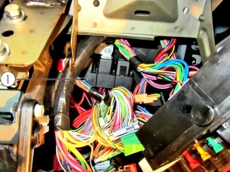
In this engine management system, the engine management system relays and fuses are located behind the mounting block under the instrument panel.
Controller Replacement
To prevent damage to the controller, when disconnecting the wire from the negative terminal of the battery or the wiring harness from the controller, the ignition must be turned off.
Remove controller
Turn off the ignition.
Disconnect the wire from the negative terminal of the battery.
Unscrew the nuts securing the controller and remove the controller by disconnecting the wiring harness blocks from it.
Only remove the pads from the controller when the controller is removed.
In the event of a controller malfunction, a "clean" controller must be used for replacement.
Installing the controller
Connect the wiring harness pads to the controller.
Install the controller on the car.
Connect the wire to the negative terminal of the battery.
Checking if the controller is working
After replacing the controller or resetting the controller using the scan tool (mode "5 - Advanced tests; 1 - ECU reset with initialization"), the throttle zero adaptation procedure and the misfire diagnostic function adaptation procedure must be performed.
Throttle Zero Adaptation Procedure:
- - when the car is stationary, turn on the ignition, wait 30 seconds, turn off the ignition, wait for the main relay to turn off.
Adaptation will be aborted if:
- - the engine scrolls;
- - car is moving;
- - accelerator pedal pressed;
- - engine temperature below 5 °С or above 100 °С;
- - ambient temperature is below 5 °С.
Procedure for adapting the misfire diagnostic function:
- - warm up the engine to operating temperature (monitored parameter TMOT_W = 60-90 °С);
- - accelerate the car in 2nd gear until the increased crankshaft speed is reached (NMOT_W = 4000 min -1) and apply engine braking (NMOT_W = 1000 min -1);
- - perform engine braking six times in one trip.
Perform diagnostics (see the procedure in card A "Checking the diagnostic circuit").


