The electronic engine control system (ECM) consists of a controller, sensors for engine and vehicle operation parameters, as well as actuators
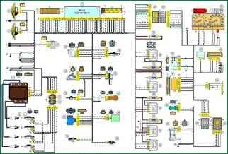
Electrical control system wiring diagram: 1 - controller; 2 - electric fan of the engine cooling system, right; 3 - electric fan of the engine cooling system, left; 4 - ignition module; 5 - spark plugs; 6 - nozzles; 7 - resistor; 8 - block of the ignition system harness to the injector harness; 9 - block of the injector harness to the ignition system harness; 10 - oil pressure warning lamp sensor; 11 - mass air flow sensor; 12 - coolant temperature sensor; 13 - throttle position sensor; 14 - idle speed regulator; 15 - oxygen sensor; 16 - crankshaft position sensor; 17 - knock sensor; 18 - solenoid valve for adsorber purge; 19 - coolant temperature indicator sensor; 20 - additional relay; 21 - right electric fan relay; 22 - fuse for the power supply circuit of the right electric fan; 23 - left electric fan relay; 24-fuse for the power supply circuit of the left electric fan; 25 - electric fuel pump relay; 26 - fuse for the power supply circuit of the electric fuel pump; 27 - ignition relay fuse; 28 - ignition relay; 29 - controller power circuit fuse; 30 - block of the ignition system harness to the instrument panel harness; 31 - block of the instrument panel harness to the ignition system harness; 32 - ignition switch; 33 - automobile anti-theft system; 34 - vehicle speed sensor; 35 - electric fuel pump; 36 - instrument cluster; 37 - mounting block; 38 - diagnostic block; 39 - block of control lamps; 40 - block of the instrument panel harness to the rear harness; 41 - rear harness block to instrument panel harness; A - to the "minus" terminal of the battery; B - to the "plus" terminal of the battery; C1, C2 - grounding points of the ignition system harness; C3 - ground point of the instrument panel harness; C4 - grounding point of the rear harness.
The wires in this diagram have a letter designation of color and a designation of the number of the circuit element to which this wire is connected. Through the fraction indicates the contact number of the block. The symbol "S28" or "SB" means that the wire is connected to the circuit element numbered 28 or marked with the letter B through a connection point not shown in the diagram
The controller is a mini-computer for special purposes, it consists of random access memory (RAM), programmable read-only memory (PROM) and electrically reprogrammable memory (EPROM).
RAM is used by the microprocessor to temporarily store current information about the operation of the engine (measured parameters) and calculated data.
Also, fault codes are written to the RAM.
This memory is volatile, i.e. when the power is interrupted (disconnecting the battery or disconnecting the wiring harness block from the controller), its contents are erased.
EPROM stores the engine control program, which contains a sequence of operating commands (algorithms) and calibration data (settings).
PROM determines the most important parameters of engine operation: the nature of the change in torque and power, fuel consumption, ignition timing, composition of exhaust gases, etc. PROM is non-volatile, i.e. the contents of its memory do not change when the power is turned off.
ERPROM stores controller, engine and vehicle IDs.


