")
")
")
")
")
")
On cars of configurations 55 and 34, the Norma power package remote control system (SDUEP) is installed
SDUEP "Norma" is intended for:
- - remote locking / unlocking of door locks with simultaneous switching on / off of the car security mode;
- - lock all doors by turning the key in the driver's door lock;
- - lock / unlock all doors with a button on the driver's door;
- - turn on an alarm in case of violation of the car's security zones;
- - turn off the alarm remotely or after turning on the ignition with your key.
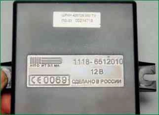
SDUEP "Norma" consists of an electrical package control unit and a remote control (RC)
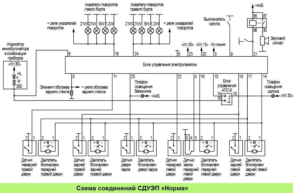
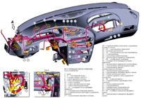
Scheme of connections SDUEP "Norma" is shown in fig. 3.
Addresses of the output plugs of the power package control unit "Norma":
Plug number - Address (plug destination)
- 3 - ECM, terminal "71", (W-line)
- 4 - Driver's door lock sensor
- 5 - Rear window heating element
- 6 - Body
- 8 - Instrument cluster, immobilizer indicator
- 9 - Hood switch
- 10 - Rear passenger door sensors
- 11 - Passenger front door sensor
- 14 - All door locks, lock motors (power)
- 15 - APS-6 control unit, contact "14"
- 16 - Port direction indicators
- 17 - Passenger door locks, lock motors (control signal)
- 18 - Driver's door lock, lock motor (control signal)
- 20 - Ignition switch, terminal "15"
- 21 - Contact "86" horn relay (coil)
- 22 - Driver's door sensor
- 23 - Battery, "+" terminal
- 24 - Starboard direction indicators
- 25 - Tailgate sensor
The remote control combines the following functions:
- - ignition key;
- - door lock key;
- - APS-6 immobilizer working key;
- - remote control for electric package.
For the remote control to work as part of the SDUEP, it must be trained using the learning key from the immobilizer (see "Learning the immobilizer").
After learning, the remote control is also a working key of the immobilizer and serves to remove the prohibition of starting the engine.
Functions of the "Norma" EMS
Locking door locks and arming from the remote control
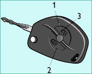
To lock the door locks and activate the armed mode, press the lock button on the remote control, fig. 4.
At the same time, the locks of the side doors and the lock of the tailgate (trunk lid) (in the variant version) will be blocked, and the armed mode will be activated at the same time, which is confirmed by a single flash of the direction indicators and a slow flash of the immobilizer signaling device in the instrument cluster.
If any door or hood is opened when arming, the direction indicators will flash three times and a single beep will sound.
To include open zones in the guard zone, close them. A similar behavior of the system will be in case of overheating protection of the door locks, if the locking / unlocking of the locks occurs repeatedly within a short period of time.
In this case, wait a while, after which the system will be fully restored.
Lock locks without arming with remote control.
To lock the door locks with remote control without arming, press the lock button twice or hold it down for a while. In this case, the doors will be blocked without arming.
Such blocking is accompanied by three flashes of direction indicators.
If the armed mode is already on, then double-clicking the lock button or holding it down will turn off the armed mode, while the door locks will remain locked.
Disarming is accompanied by double flashing of direction indicators.
Unlocking door locks and disarming from the remote control
Press the unlock button to unlock the driver's door and disarm from the remote control. The driver's door lock is unlocked, and disarming is accompanied by a double flashing of the direction indicators.
Press the unlock button on the remote again to unlock the passenger doors.
If, after unlocking the doors and turning off the security mode, none of the doors is opened and the ignition is not turned on, then after 25 seconds the doors will be locked again and the system will automatically switch to the armed mode.
Automatic transition of the system to armed mode with door locking is accompanied by frequent flashing of the immobilizer indicator in the instrument cluster.
Attention! If the security mode is not disengaged from the remote control due to a drop in battery voltage in the remote control, it is possible to open the door with a key. This will trigger an alarm that can be turned off by turning on the ignition.
Further operation of the car will be carried out without the possibility of turning on the alarm.
Central locking and unlocking of the doors from the passenger compartment
To lock all doors from inside the car, push the lock button into the driver's door.
To unlock the driver's door, lift the lock button on the driver's door.
Press the unlock button on the remote control to unlock all the doors from inside the car.
The central locking has protection of the door locks against overheating. If locking and unlocking occurs repeatedly within a short period of time, the system stops responding to button presses.
If this happens, do not press the button for a while, after which the system will fully recover. For security purposes, the last command executed is always the unlock command.
Central locking of door locks from outside the car
To lock all doors outside the vehicle, turn the key in the driver's door lock counterclockwise.
When the key is turned clockwise, the central unlocking of all doors does not occur, only the door that is currently opening is unlocked.
The system is armed.
After arming, the system monitors the status of the following armed zones:
- - side doors;
- - hood;
- - tailgate;
- - ignition switch;
- - driver's door lock;
- - battery voltage;
- - additional sensor (not included in the factory package).
If any of the following occurs while armed:
- - opening any side door;
- - hood opening;
- - opening the tailgate;
- - turn on the ignition without using "your" key;
- - unlocking the driver's door;
- - connecting the battery after disconnecting it;
- then an alarm is activated in the form of a light signal with direction indicators and an audible signal with a regular sound signal of the car for about 30 seconds.
A single press of any button on the remote control when the system is in alarm mode will stop the alarms, but the system will remain armed.
Disarming occurs after pressing the unlock button on the remote control.
Resynchronization of remote control codes
If you press the buttons of the remote control outside the coverage area of the radio channel, the counter of the "floating" code in the remote control goes out of synchronization with the counter in the system control unit.
If the number of remote control button presses outside the signal reception area of the system exceeds 1000, the system will stop responding to remote control commands. In this case, the immobilizer training procedure should be repeated.
Replacing a faulty electric package control unit
In the event of a malfunction of the power package control unit, after replacing it, carry out the immobilizer training procedure with your “own” learning key.
In the event of a malfunction in the system, the corresponding malfunction code is entered in the memory of the power package control unit. The list of SDUEP fault codes is given in the table
List of SDUEP fault codes
Code - Description
- B1001 - Low battery voltage
- B1002 - High voltage during operation of geared motors
- B1003 - Insufficient current when gearmotors operate
- B1004 - Overcurrent when gearmotors operate
- B1005 - Insufficient current when the direction indicators are activated
- B1006 - Overcurrent when the direction indicators are activated
- B1007 - Malfunction in the horn circuit
- B1008 - Overheating of gearmotors
- B1014 - Unexpected Receiver Chip Reset
- В1015 - No connection with KSUD
- B1016 - Error writing/reading internal EEPROM
- В1017 - Remote control counter out of sync
- B1018 - Reset CU
For the diagnosis of SDUEP, the DST-2, 10.12 diagnostic device with the appropriate firmware is used.
When selecting the "Electropackage" system, the diagnostic tool allows you to view fault codes in the "Faults" mode, system parameters in the "Parameters" mode, and also control individual devices (lock motors, horn relays) in the "IM control" mode.
Causes of malfunctions and methods for their elimination
B1001 Battery voltage low
- The power supply voltage of the power package control unit is below 10 V.
- Check the voltage at the battery terminals. The voltage should be between 13.2-14.9 V.
- Check the voltage on terminals "23" and "20" of the electric package control unit, it should be equal to the battery voltage.
- Check the grounding (pin 6) of the electrical control unit.
B1002 High voltage during operation of geared motors
- The power supply voltage of the power package control unit is more than 16 V.
- Check the voltage at the battery terminals. The voltage should be between 13.2-14.9 V.
B1003 Insufficient current when gearmotors operate
- An open in the control circuit of one or more door lock motors.
- Check for operation of the motors of all doors: select on the diagnostic tool "Electrical package" → "MI control" → "Common Wire Motored" - lock all doors, "Motored Door Water" - unlock the driver's door, "Motored Door Water" - passenger door unlocking.
- Check the non-working gearmotor and the chain to it for an open circuit (data for checking the gearmotor see "Door Lock System")
B1004 Overcurrent when gearmotors operate
- Short circuit in the control circuit of one or more door lock motors.
- Check for actuation of the motors of all doors: select on the diagnostic tool "Electrical package" → "MI control" → "Common Wire Motored" - lock all doors, "Motored Door Water" - unlock the driver's door, "Motored Door Water" – Unlock passenger doors.
- Check the non-working gearmotor and the circuit to it for a short circuit (data for checking the gearmotor, see "Door Lock System")
B1005 Insufficient current when the direction indicators are activated
- An open in the direction indicator control circuit.
- Turn on the turn signals: select on the scan tool "Electrical package" → "MI control" → "Left turn signal", "Right turn signal".
- Check the direction indicator control circuits (terminals "16" and "24" of the control unit) for an open circuit.
- Check the integrity of the direction indicator bulbs.
B1006 Overcurrent when turn signal is activated
- Short circuit in the direction indicator control circuit.
- Check the direction indicator control circuits (terminals "16" and "24" of the control unit) for a short circuit.
B1007 Failure in the horn circuit
- An open in the control circuit of the horn relay.
- Turn on the horn: select on the diagnostic tool "Electrical package" → "IM control" → "SoundBeep"
- Check the sound signal and the circuit to it (terminal "21" of the control unit) for an open circuit.
B1008 Gearmotor overheating
- Overheating of gearmotors due to a large number of operations.
- Do not use the "lock / unlock" mode of the door locks for a while.
B1014 Unexpected receiver chip reset
- Internal error of the control unit.
- Turn off the ignition, completely disconnect the power from the SDUEP control unit. If the code is re-entered, replace the SDUEP control unit.
В1015 No connection with KSUD
- Break in the "W-line" circuit.
- Check the circuit to the ECM (terminal "3" of the control unit) for an open.
B1016 Error writing / reading internal EEPROM
- Internal error of the control unit.
- Switch off for burning, completely disconnect the power supply from the SDUEP control unit. If the code is re-entered, replace the SDUEP control unit.
B1017 RC counter out of sync
- The number of remote control button presses outside the system signal reception area has exceeded 1000.
- Perform the immobilizer learning procedure again.
B1018 CU reset
- Loss of power supply of the power pack control unit.
- Check the supply voltage at "23" and "20" of the power package control unit, the reliability of the connections in the block to the control unit.
- Check the grounding (terminal "6") of the electrical control unit.
Removing and installing the electric package control unit
Mount the car to the workplace, brake with the parking brake, turn off the ignition and disconnect the minus terminal from the battery.

With a Phillips screwdriver, unscrew the two screws and remove the cover of the interior mounting block

Use a Phillips screwdriver to unscrew the mounting block fastening screw

We remove the block holder "B" from the bracket "A" and lower the mounting block down

With a 10 head, unscrew the two nuts securing the block and remove the block from the studs

By pressing the latches of the block, we disconnect the block of wires from the block connector
Replacing the battery in the car key remote control
The key contains a CR2032 type battery with an initial voltage of 3 V.
If the battery voltage is normal, then when you press any button on the remote control, the LED should flash once.
When pressing any button on the remote control, the LED flashes twice or does not light up at all, this indicates that the battery needs to be replaced

Prying with a thin screwdriver, remove the plug from the cover of the remote control
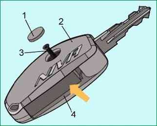
The plug is glued with double-sided tape. If the adhesive tape remains on the cover, then remove it to gain access to the self-tapping screw

Use a Phillips screwdriver to unscrew the screw securing the console cover

By pressing with your finger, we disengage the latch

Carefully separate the cover and the body of the remote control, overcoming the resistance of the second latch

Remove the cover of the remote control and remove it from the body of the key with a spring
Remove the battery from the remote control circuit board
Insert a new battery, observing the polarity
Having inserted the bent end of the spring into the groove on the remote control case, turn the key one turn counterclockwise, twisting the spring and holding the key in this position, install the cover
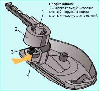
We twist the screw and install the plug