Alternator type 9402.3701-01, three-phase, with built-in rectifier unit and electronic voltage regulator, clockwise rotation (drive side)
The generator installed on the car is driven by a V-belt.
Repair work is shown on the example of a generator with a multi-stranded pulley.
All elements of both generators, except for pulleys, are absolutely identical.

The alternator armature is driven from the crankshaft pulley by a V-belt or (depending on the version) a V-ribbed belt.
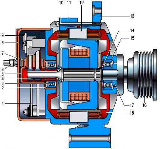
The stator 12 (Fig. 1) and covers 11 and 13 are fastened with four screws.
Rotor shaft 18 rotates in bearings 3 and 15, which are installed in the covers.
Power to the rotor winding (field winding) is supplied through brushes and slip rings 4.
The three-phase alternating current induced in the stator winding is converted into direct current by the rectifier unit 1 attached to the cover 11.
The electronic voltage regulator 9 is combined into one unit with a brush holder and is also attached to the cover 11.
The generator connection diagram is shown in fig. 2.
The voltage for excitation of the generator when the ignition is switched on is supplied to the terminal "D +" of the regulator (terminal "D" of the generator) through the control lamp 3 located in the instrument cluster.
After starting the engine, the field winding is powered by three additional diodes installed on the rectifier unit of the generator.
The output "W" of the generator on cars of the VAZ-2123 family is not used.

The operation of the generator is controlled by a warning lamp in the instrument cluster.
When the ignition is turned on, the lamp should be on, and after starting the engine, it should go out if the generator is working.
The bright burning of the lamp or its glow half-heartedly indicates malfunctions.
Generator specifications
Maximum output current (at 13 V and 6000 min -1) - 80 A;
Regulated voltage limits - 13.2-14.7 volts;
Gear ratio engine-generator - 1:2.16
If the alternator belt broke on the way, and you forgot the spare at home, a 20 mm wide ring cut from an old car chamber can temporarily replace it.
To reduce current consumption when driving a vehicle with a faulty alternator, if possible, turn off the radio, unnecessary lights, heater fan, glass heating, etc.


