The driveline is designed to transmit torque from the gearbox to the transfer case and from the transfer case to the front and rear drive shafts
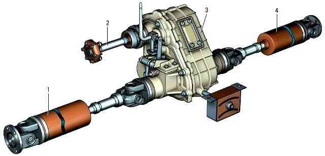
Fig. 1. Driveline
The cardan drive of the VAZ-2123 car consists of an intermediate 2 (Fig. 1), front 1 and rear 4 cardan shafts.
The intermediate cardan shaft is made of a bar with slots at both ends.
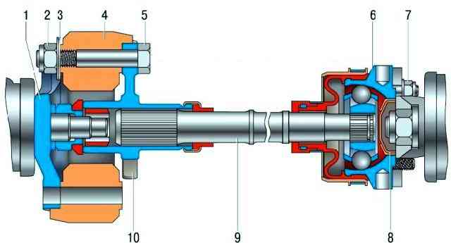
At one end of the shaft (from the side of the gearbox) there is a flange 10 (Fig. 2), which is connected to the flange 1 of the output shaft of the gearbox through an elastic coupling 4.
The spline connection between the flexible coupling flange and the shaft is sealed with an oil seal. At the other end of the shaft (from the side of the transfer case) there is a constant velocity joint.
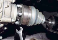
The body 6 of the constant velocity joint is attached to the flange of the transfer case drive shaft with studs.
The design of the front and rear cardan shafts is the same. The shaft is a thin-walled steel pipe.
On one side, a splined tip is welded to the pipe, on which a sliding fork of the cardan joint is installed.
The spline connection of the shaft and fork is sealed with an oil seal. On the other side, a universal joint fork is welded to the pipe.
Both universal joints are connected to flanges, one of which (from the side of the pipe) is attached to the flange of the front axle gearbox, and the other to the flange of the output shaft of the transfer case.
Each universal joint consists of two forks connected by a cross.
On parts of manufactured cars, front and rear cardan shafts with constant velocity joints can be installed.
Their design is similar to that of the front wheel drives.
Checking the correct operation of the driveline on the car
Check the cardan drive from below the vehicle on a lift or pit.
The gearbox and transfer case must be in neutral.
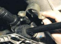
Check the reliability of the tightening of all threaded connections, the condition of the hinges and the rubber array of the flexible coupling of the intermediate shaft (external inspection).
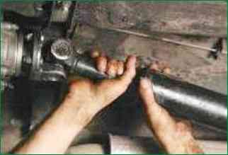
1. Grasp the shaft near the joint to be checked with both hands.
Short, sharp movements rock each driveshaft in directions perpendicular to its axis.
Perceptible play in the hinges is not allowed.
2. Repeat the test for all universal joints.
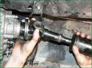
3. With short, sharp movements, turn the cardan shaft around its axis in both directions, holding the fork-flange of the cardan joint from turning.
Perceptible circumferential gaps are not allowed
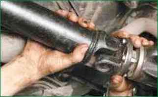
4. Repeat the check on the remaining universal joints.


