We remove the gearbox for repair, for dismantling the engine.
Preparing the car for removing the gearbox. Putting the car on a lift
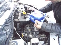
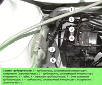
Disconnect the negative battery cable (Fig. 1). Drain the oil from the gearbox.
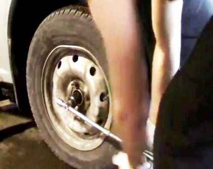
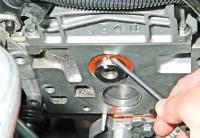
Before lifting the car on a lift, unscrew the nuts of the wheel hubs with a head of 30 on both sides (Fig. 2)
After that, we raise the car to a height convenient for doing the work.
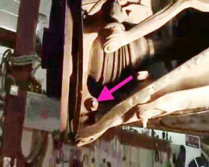
With a 16 head, unscrew the nut securing the ball joint terminal clamp (Fig. 3) (see the article - Replacing the front suspension arm Lada Largus)
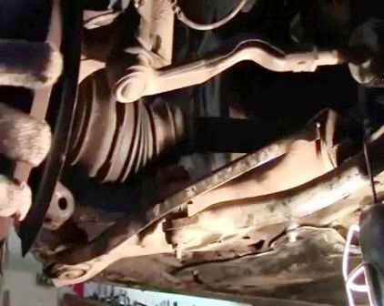
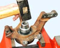
We take the rotary lever to the side (Fig. 4) and remove the wheel drive from the steering knuckle.
We perform this operation on both sides.
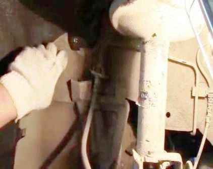
Remove the protective shields from both sides (Fig. 5)
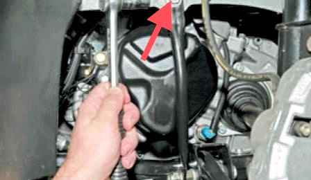
We unscrew the upper nut securing the cross member bracket to the body (Fig. 6).
We also carry out this operation on both sides.
On the right side, remove the wheel drive from the gearbox.
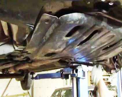
Then remove the engine protection (Fig. 7)
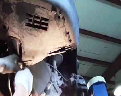
Unscrew the anthers from the bottom of the bumper (Fig. 8)
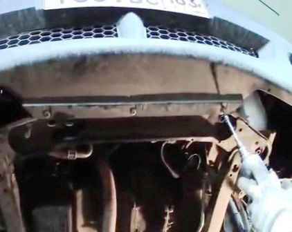
We unscrew the three screws of the lower bumper mount (Fig. 9)
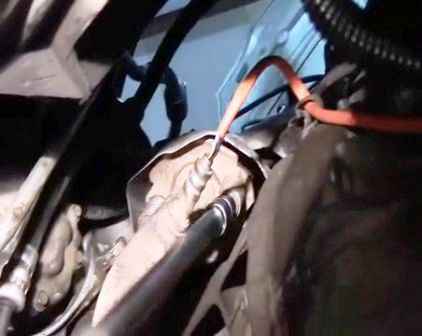
With a 10 head, unscrew the two nuts securing the intake pipe (Fig. 10)
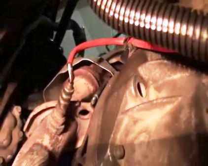
We lower the front pipe down (Fig. 11)
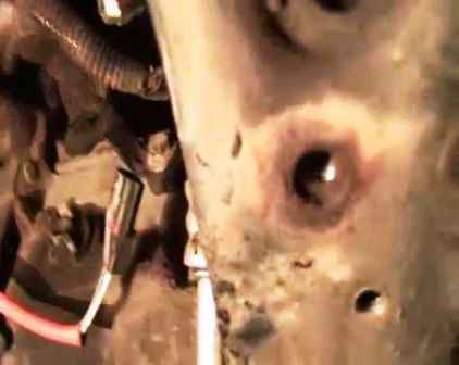
Disconnect the oxygen sensor wire chip (Fig. 12)
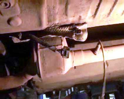
Disconnect the second oxygen sensor from the connector (Fig. 13)
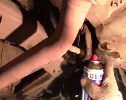
Lubricating penetrating lubricant rubber shock absorbers mounting the muffler (Fig. 14)
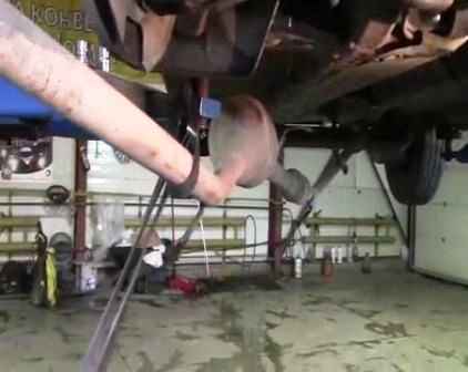
We take out the muffler pipe from the rubber shock absorbers and, moving it aside, we tie it with a technological hook or belt, it is possible by the lifter leg (Fig. 15)
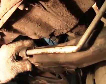
Using a 10 key, unscrew the bolt of the bracket for attaching the power steering tube to the subframe (Fig. 16)
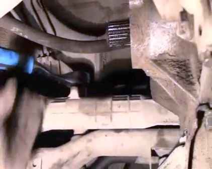
With a head of 18, we unscrew the two bolts securing the steering rack to the subframe (Fig. 17)
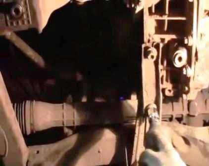
Unscrew the fastening of the rear engine mount (Fig. 18)
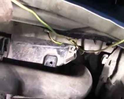
Before removing the subframe, you need to tie up the radiator of the engine cooling system in two places from above, since the radiator is inserted into the subframe (Fig. 19)
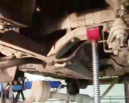
We substitute the sliding rack under the subframe (Fig. 20)
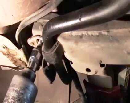
With a head of 18, we unscrew the four bolts of the subframe (Fig. 21)
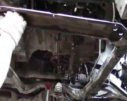
Holding the subframe, let go of the retractable stand and together with an assistant remove the subframe (Fig. 22)
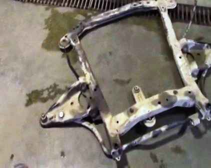
Removed subframe (fig. 23)
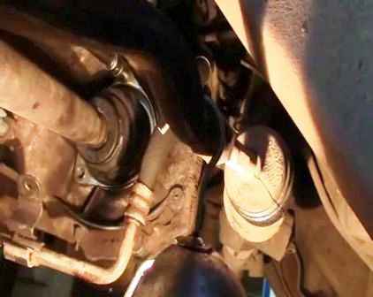
We unscrew the three bolts securing the anther of the left drive (Fig. 24)
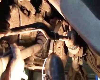
Remove the left wheel drive from the gearbox (Fig. 25)
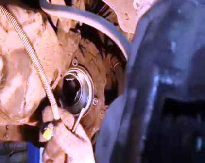
Disconnect the reverse sensor wire connector (Fig. 26)
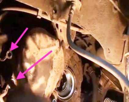
Using a 13 head, unscrew the two bolts securing the two ground wires (Fig. 27)
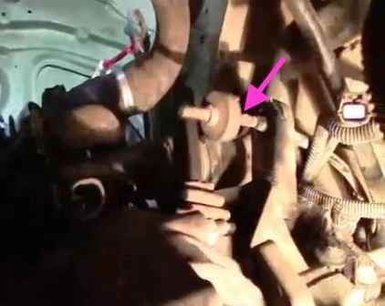
Disconnect the clutch cable from the clutch fork (Fig. 28)
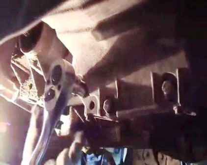
Using a 13 head, unscrew the four lower bolts securing the pallet to the gearbox (Fig. 29)
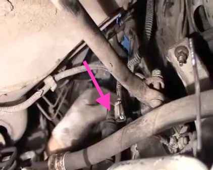
Press the lock and disconnect the speed sensor connector (Fig. 30)
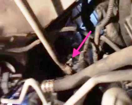
With a key of 13, we loosen the bolt of fastening the thrust of the gearbox backstage (Fig. 31)
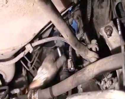
Disconnect the backstage linkage and move the linkage to the side (Fig. 32)
Using a 13 key, we unscrew the two starter mounting bolts.
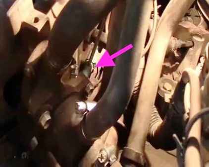
Remove the crankshaft sensor connector (Fig. 33)
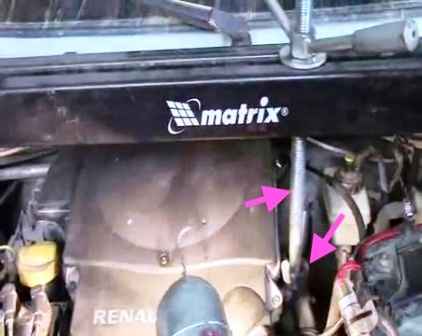
We install the traverse and hang the engine by the eye (Fig. 34)
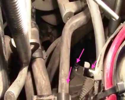
Using a 16-head with an extension, unscrew the three bolts securing the bracket of the left engine mount (Fig. 35)
Release the hook of the traverse, which holds the engine by the eye, and lower the engine.
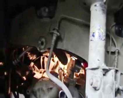
Now we have access to the third starter bolt, and we unscrew it (fig. 36) with a 13 head with an extension.
And unscrew two more gearbox mounting bolts.
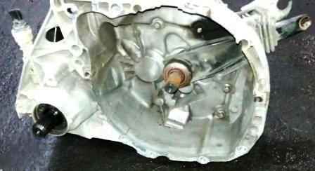
We unscrew the two nuts securing the gearbox, and shaking a little together with an assistant, remove the gearbox.
Install the gearbox in reverse order.
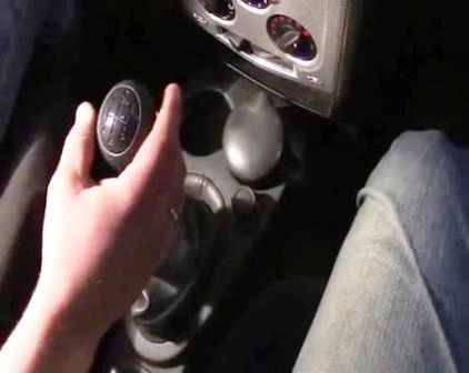
To correctly set the linkage of the backstage, you need to set the gearshift lever to the position corresponding to the neutral position of the gearbox (Fig. 37).
In this position, the assistant must hold the lever in this position.
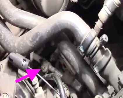
At this point, you need to tighten the nut of the backstage link clamp (Fig. 38).
Tightening torques for mounting the gearbox:
- Mounting studs - 6.5 Nm
- Top gearbox mounting bolts - 44 Nm
- Lower gearbox mounting bolts - 44 Nm
- Manual gearbox mounting nuts - 44 Nm
- Ground bolt to clutch housing - 44 Nm
- Ground bolt on gearbox housing cover - 21 Nm
- Wheel bolt - 105 Nm
- Tie rod mounting bolt - 21 Nm
- Gearbox oil drain plug - 25 Nm
- LH drive inner CV joint boot holder bolts - 25 Nm
- Subframe bolt - 105 Nm
- Knuckle bolt nuts to the shock absorber strut - 105 Nm
- Hub nut - 280 Nm
Left power unit support:
- Bolts - 35 Nm
- Nuts - 50 Nm


