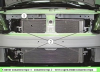
The anti-lock braking system provides more effective braking of the car by reducing fluid pressure in the brakes at the time of their blocking
The fluid from the brake master cylinder enters the ABS unit, and from there it is supplied to the brake mechanisms.
The hydraulic unit itself is mounted on the right side member, near the bulkhead, consists of a modulator, a pump and a control unit.
The block operates depending on the readings of the wheel speed sensors.
When the car is braking, the ABS unit detects the beginning of wheel lock and opens the corresponding modulator solenoid valve to relieve the pressure of the working fluid in the channel.
The valve opens and closes several times per second to make sure the ABS is working by the slight trembling of the brake pedal when braking.
Removing the ABS unit
We install the car on a lift or a viewing hole. Disconnect the negative battery terminal.
We unscrew the three nuts securing the soundproofing to the front panel and the right mudguard and move the soundproofing to gain access to the hydraulic unit (flat screwdriver).
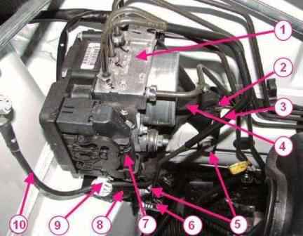
Removing the ABS hydraulic unit: 1 - ABS hydraulic unit; 2 - bracket for fastening the front wiring harness on the valve body bracket; 3 - brake tube; 4 - front wiring harness; 5 - bolts for fastening the valve body bracket; 6 - bracket for fastening the brake pipe on the valve body bracket; 7 - plug block of the front wiring harness; 8 - valve body mounting bracket; 9 - bracket for attaching the ground wire to the valve body bracket; 10 - ground wire
Disconnect plug 7, Figure 1, of the front wiring harness from the hydraulic unit.
Disconnect the brake pipes from the hydraulic unit of the anti-lock brake system.
We install plugs in the holes of the hydraulic unit and on the brake pipes (key for brake pipes, technological plugs).
We remove the front wire harness 4 from bracket 2, ground wire 10 from bracket 9 and brake pipe 3 from bracket 6 of attachment to the bracket of the hydraulic unit.
Unscrew the bolts 5 securing the hydraulic unit bracket to the body and remove the hydraulic unit 1 complete with the bracket 8.
We unscrew the bolts securing the hydraulic unit to the mounting bracket and remove the hydraulic unit (replaceable head 10, ratchet wrench).
Installation
Attention. When replacing the hydraulic unit, perform the ABS computer programming procedure.
To ensure the tightness of the connector of the hydraulic unit control unit, the terminal of the ground wire of the hydraulic unit must be oriented downwards.
Install the hydraulic unit on the mounting bracket and secure with bolts. Bolt tightening torque 8 Nm (0.8 kgf.m).
Install the hydraulic unit assembly with the bracket on the vehicle and secure with bolts. Bolt tightening torque 22 Nm (2.2 kgf.m).
Connect the connector of the front wiring harness to the hydraulic unit connector.
Install the wiring harness, ground wire and brake pipe into the mounting brackets on the hydraulic unit bracket (flat screwdriver).
Remove the technological plugs from the openings of the hydraulic unit and the brake pipes and connect the brake pipes to the hydraulic unit. The tightening torque of the fittings is 14 N.m (1.4 kgf.m).
Connect the ground wire terminal to the battery.
Bleed the brake system.
Removing and installing the front wheel speed sensor
Withdrawal
Remove the front wheel. We raise the car to a height convenient for work.
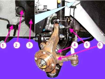
Removing the front wheel speed sensor: 1 - fastening bracket for the speed sensor wiring harness; 2 - arch cover retainer; 3 - casing of the front wheel arch; 4 - front wheel speed sensor; 5 - bracket for fastening the speed sensor wiring harness on the front suspension strut; 6 - knuckle
We remove the retainer 2, Figure 2, of the protective cover of the front wheel arch in the area where the speed sensor wiring harness is located.
We remove the speed sensor wire harness from the grooves of the bracket 5 of the front suspension strut and from the holder 1 on the mudguard of the engine compartment.
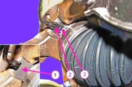
Removing the front wheel speed sensor: 1 - insulating foam; 2 - front wheel speed sensor; 3 - retainer
Removing the insulating foam Figure 1, Figure 3, from the knuckle speed sensor mounting socket.
We remove the 2nd speed sensor from the mounting hole on the steering knuckle by pressing the tab of the 3rd sensor lock with a screwdriver.
Disconnect the speed sensor wiring harness connector from the front wiring harness and remove the sensor.
Installation
The insulating foam of the wheel speed sensor must be replaced.
Install the insulating foam into the knuckle speed sensor mounting slot.
Connect the speed sensor wiring harness connector to the front wiring harness.
Install the speed sensor in the mounting hole on the steering knuckle until the latch is released.
Install the speed sensor harness into the grooves of the front suspension strut bracket and into the holder on the engine compartment mudguard.
Fix the front wheel arch protection cover with a retainer.
Install the front wheel.
Removing and installing the rear wheel speed sensor
Withdrawal
Remove the rear wheel.
Raise the vehicle to a comfortable height for work.
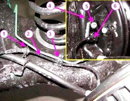
Removing the rear wheel speed sensor: 1 - mounting bracket for the speed sensor wiring harness; 2 - speed sensor wiring harness; 3 - latch; 4 - rear brake shield; 5 - speed sensor mounting bolt; 6 - rear wheel speed sensor
Remove the harness 2, figure 4, of the speed sensor wires from the groove of the bracket 1 and from the retainer 3 on the rear suspension arm.
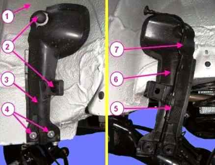
Removing the rear wheel speed sensor: 1 - rear wheel arch; 2 - clamps for fastening the casing; 3 - protective casing of the speed sensor wiring harness; 4 - casing fastening nuts; 5 - block of the wiring harness of the speed sensor; 6 - protective casing in the deployed position; 7 - rear wiring harness
Remove bolt 5 fastening the speed sensor to the rear brake shield and remove sensor 6.
Unscrew the two nuts 4, figure 5, securing the cover of the protective wiring harness of the rear wheel speed sensor.
Remove the two clips 2 securing the cover and unfold the cover 3 (6) to gain access to the speed sensor wiring harness block.
Remove the speed sensor wiring harness from the casing holders, disconnect the sensor harness connector 5 from the rear wiring harness 7 and remove the sensor.
Connect the speed sensor wiring harness connector to the rear ABS wiring harness, and fix the sensor wiring harness in the housing holders.
Reinstall the speed sensor wiring harness cover and secure it to the rear wheel arch with two clamps and two nuts. Nut tightening torque 14 Nm (1.4 kgf.m).
Installation
Install the speed sensor in the hole in the brake shield and secure it with the bolt. Bolt tightening torque 14 Nm (1.4 kgf.m).
Install the speed sensor harness into the groove of the bracket and into the holder on the rear suspension arm.
Install the rear wheel.


