Oil pump (Fig. 1.) gear type installed inside the oil sump
The pump is attached with two studs to the ramps on the third and fourth baffles of the cylinder block.
The accuracy of the pump installation is ensured by two bushing pins pressed into the cylinder block.
Pump housing 4 is cast from aluminum alloy, gears 3 and 6 have straight teeth and are made of cermet (sintered metal powder).
Drive gear 3 is fixed on shaft 5 with a pin.
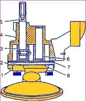
A hexagonal hole is made at the upper end of the roller, into which the oil pump drive shaft enters.
Driven gear 6 rotates freely on an axle pressed into the pump housing.
The cover 2 of the pump is made of gray cast iron and is attached to the pump with four bolts.
There is a 0.3 mm thick cardboard pad under the lid.
The oil receiver and the intake pipe of 1 oil pump are made in a single housing made of aluminum alloy.
A mesh is rolled on the receiving part of the nozzle.
The branch pipe is attached to the oil pump with four bolts together with the oil pump cover through the paronite gasket 8.
The performance of the oil pump is much higher than required by the engine.
The performance margin is necessary to ensure the appropriate oil pressure in the system at any engine operating mode.
At the same time, excess oil flows from the discharge cavity of the pump through the pressure reducing valve back into the suction cavity.
With an increase in oil consumption through the gaps in the bearings (if the engine wears out), the required pressure is also maintained in the system, but in this case, a smaller amount of oil passes through the pressure reducing valve back into the pump intake cavity.
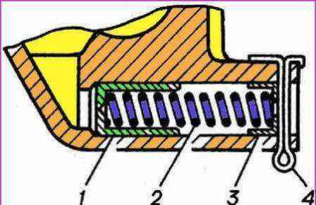
The plunger-type pressure reducing valve is located in the oil pump housing.
The end of plunger 1 (Fig. 2.) is affected by oil pressure, under the influence of which the plunger, overcoming the force of spring 2, moves.
When a certain pressure is reached, the plunger opens the drain channel opening, passing excess oil into the pump intake cavity.
The pressure reducing valve spring rests on a flat washer 3 and is fastened with a cotter pin 4, passed through the holes in the lug on the pump housing.
Reducing valve is not adjustable; the required pressure characteristic is provided by the geometric dimensions of the pump housing and the characteristic of the spring: to compress the spring to a length of 40 mm, a force of 43.5–48.5 N (4.35–4.85 kgf) is required.
In operation, it is not allowed to change the spring force of the pressure reducing valve in any way.
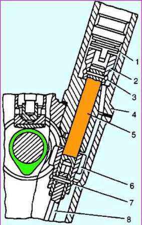
The drive of the oil pump and the ignition distribution sensor (Fig. 3.) is carried out from the camshaft by a pair of helical gears.
The drive gear is steel, cast into the body of the cast-iron camshaft.
Driven gear 8 is made of steel, heat-strengthened, fixed with a pin on roller 5, rotating in a cast-iron housing.
The upper end of the roller is equipped with a sleeve 2, which has a slot (displaced by 1.15 mm from the axis of the roller) for driving the ignition distributor sensor.
The sleeve on the roller is secured with pin 3.
A hexagonal roller 10 is pivotally connected to the lower end of the roller, the lower end of which enters the hexagonal hole of the oil pump roller.
During rotation, gear 8 is pressed against the end of the cast-iron drive housing through thrust washers 6 and 7.
This assembly, as well as the roller in the drive housing, is lubricated with oil sprayed by the drive gears and flowing down the block wall.
The oil flowing down the walls enters the slot (trap) on the lower end of the drive housing and then through the hole onto the surface of the roller.
A spiral groove is cut into the hole for the roller in the drive housing, through which the oil when the roller rotates, it rises up and is evenly distributed along its entire length.
Excess oil from the upper cavity of the drive housing is drained back to the crankcase through the drain hole in the housing.
The correct position of the ignition distributor on the engine is ensured by such an installation of the drive in the block, in which at the moment the piston of the first cylinder is at TDC (compression stroke), the slot on the drive sleeve is parallel to the engine axis at the maximum distance from it.


