We remove the clutch discs for inspection, repair or replacement
Removing the clutch discs
Remove the manual transmission
Remove the cover of the clutch release fork
Remove the clutch release fork assembly
Remove the clutch release bearing clutch clamp
Remove the clutch release fork support from the gearbox
Apply mounting marks on the clutch cover and flywheel
We unscrew each bolt at one time for one turn, until the spring force is weakened
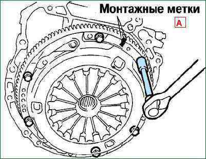
Unscrew the clutch cover bolts
Remove the slave and master disks
Clutch test
Use a vacuum cleaner or a clean cloth to remove dust from the clutch cover
Check the condition of the friction surface of the flywheel for cracks, burn marks and surface wear
Check the condition of the friction linings of the clutch driven disk and if they have traces of oil or mechanical damage, replace the driven disk
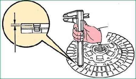
Check the thickness of the clutch disc lining using a vernier caliper.
The overlays must protrude above the heads of the rivets by at least 0.3 mm
If the thickness of the pads is less than acceptable or the rivet heads are close to the working surface, replace them or the clutch disc.
Check that the springs are not broken or cracked.
Check for wear on the splines in the hub of the clutch disc
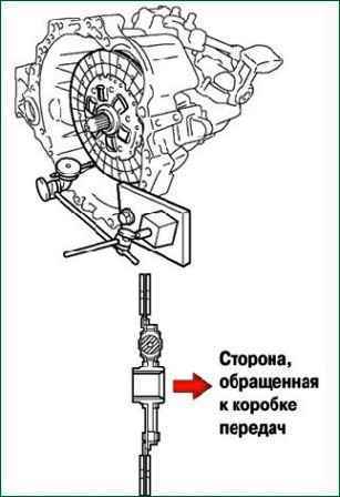
Install the clutch disc on the gearbox shaft
The clutch disc should slide easily and smoothly on the splines of the input shaft of the gearbox
If you need to replace the driven disk, then you must also replace the clutch release bearing
Using a dial indicator, check the runout of the clutch disc
Minimum runout 0.8 mm
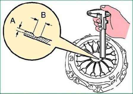
Using a vernier caliper, we check the depth and width of the wear of the petals of the diaphragm spring
Maximum:
- A (depth): 0.5 mm;
- H (width): 6.0 mm
Slight damage to the friction surface can be removed with fine sandpaper
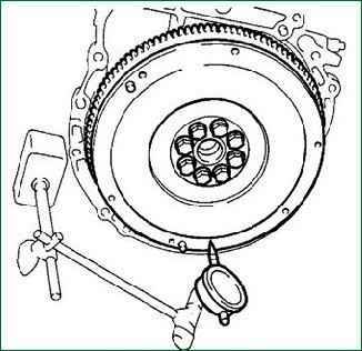
Using a dial gauge to check flywheel runout
Maximum runout - 0.1 mm
Checking the clutch release bearing
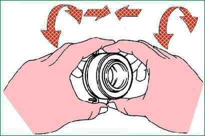
We rotate the clutch release bearing by hand, applying force in the axial direction, we check the release bearing
The bearing is lubricated for life, no additional lubrication is required
Installing clutch discs
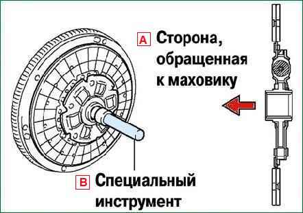
We insert the special tool into the clutch disc, then install the disc on the flywheel
Align the mounting marks on the clutch cover and flywheel.
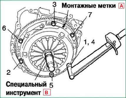
We tighten six bolts, starting with the bolt located near the pin on top.
Acting in the order shown in the figure, at the same time evenly tighten the bolts. Tightening torque 19.1 Nm
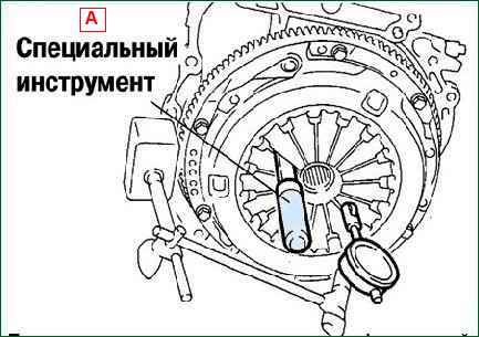
Using a dial indicator with a roller, check the alignment of the diaphragm spring petals
Maximum mismatch is 0.5 mm
Install the clutch release fork support into the gearbox. Tightening torque - 47.1 Nm
Install the clamp of the clutch release bearing on the bearing
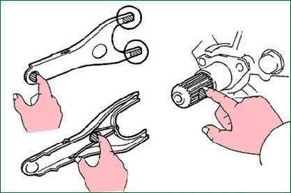
Apply grease to the contact surfaces of the clutch and the clutch release fork, the fork and pushrod and the fulcrum of the fork
Applying grease to the splines of the clutch and to the splines of the input shaft
Lubricant: P/N 08887-01806 Clutch Release Grease or equivalent
Installing the clutch release fork with the clutch release bearing into the gearbox
After installation, move the fork back and forth to check the smooth movement of the release bearing
Installing the cover of the clutch release fork
Installing the gearbox


