")
")
")
")
")
")
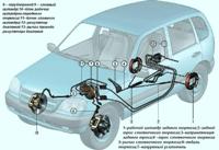
All control devices of the car are combined in the instrument cluster
It includes: an electronic speedometer and tachometer, a liquid crystal indicator of the total and daily mileage counter (odometer), a liquid crystal indicator of hours and ambient temperature, a coolant temperature gauge, a fuel gauge, twelve control lamps and six backlight lamps.
The operation of the devices is controlled by an electronic module, which receives signals from sensors.
Temperature and fuel gauges are magnetoelectric type.
The tachometer and speedometer needles are driven by stepper motors.
The electronic instrument cluster cannot be repaired, except for the replacement of control lamps and instrument lighting lamps.
Components of the instrument cluster are not supplied as spare parts.
Therefore, in case of failure of one of the devices, the combination should be replaced as an assembly.
To avoid damaging the instrument cluster glass, do not clean it with any solvents.
You can wash it with mild soapy water. It is best to use a glass cleaner, such as Sekunda.
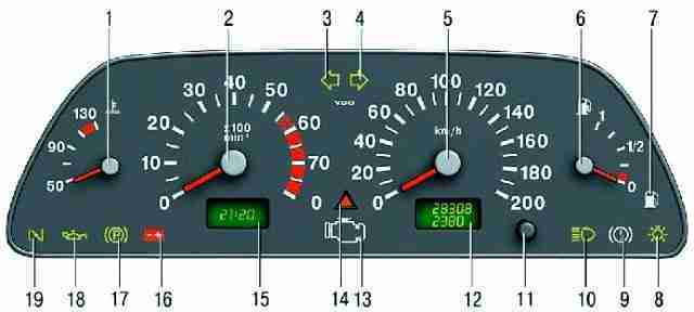
Instrument cluster: 1 - coolant temperature gauge in the engine cooling system; 2 - an electronic type tachometer shows the engine crankshaft speed; 3 - the control lamp for turning on the left direction indicator (with a green light filter in the form of an arrow) lights up with a flashing light when the left direction indicator is turned on synchronously with it; 4 - control lamp for turning on the right direction indicator (see paragraph 3); 5 - induction type speedometer shows the speed at which the car is currently moving; 6 - fuel level indicator of the electromagnetic principle of operation; 7 - control lamp of the minimum fuel reserve in the tank (with an orange light filter); 8 - control lamp for turning on the side light (with a green light filter); 9 - signal lamp of the emergency state of the brake system (with a red light filter); 10 - control lamp for switching on the main beam of headlights (with a blue light filter); 11 - button for resetting the readings of the daily counter of the distance traveled, switching the indication of time and ambient temperature and setting the time; 12 - electronic type mileage indicator; The top line of the indicator shows the total mileage of the car, and the bottom line shows the daily mileage; 13 - control lamp of the engine management system (with an orange color filter) "Check engine" ("Check the engine"); 14 - control lamp for turning on the alarm (with a red light filter); Lights up with a flashing light when the alarm is turned on; 15 - indicator of time and temperature; 16 - signal lamp of the battery discharge (with a red light filter); 17- control lamp for turning on the parking brake (with a red light filter); 18 - signal lamp for emergency oil pressure drop (with red light filter); 19 - reserve
Technique for Troubleshooting Instruments
When the arrow of the coolant temperature gauge is constantly at the beginning of the scale, with the ignition on, disconnect the wire from the gauge sensor and connect the wire end to ground.
If the arrow deviates, then the sensor is faulty and must be replaced, and if it does not deviate, then check the pointer in the instrument cluster and the wire connecting the sensor and pointer.
If the temperature gauge is faulty, replace the instrument cluster.
The procedure for checking the fuel gauge is similar to that described above.
If the pointer needle is constantly at the beginning of the scale and does not deviate after the wire tip disconnected from the sensor is shorted to ground, then check the pointer.
If the fuel gauge is faulty, replace the instrument cluster.
Removal and installation of the instrument cluster is described in the article - Removal and installation of the Niva Chevrolet instrument cluster
Checking appliances
The instrument cluster has a built-in self-diagnosis system. This system allows you to test the instrument cluster on the car.
- 1. With the ignition off, press and hold the trip odometer reset button.
Turn on the ignition and release the button. After that, the instrument cluster switches to the “test” mode: the arrows of all instruments move three times over the entire range of the scale and all segments of the liquid crystal indicator (LCD) are displayed.
- 2. Clear the electronic instrument cluster processor memory by pressing the odometer reset button for at least 5 seconds.
- 3. Swipe again ry testing.
After that, briefly press and release the odometer reset button.
The LCD will display the processor software version number (Uer 0.8, Uer 1.1 or other).
Pressing the reset button again will display one of the following codes:
- 0 - no faults;
- 1 - the microprocessor is faulty;
- 2 - open circuit of the fuel gauge sensor;
- 4 - increased voltage in the on-board network (more than 16 + 1.8 V);
- 8 - low voltage in the on-board network (less than 8–0.6 V).
If there are several faults, the corresponding sum of codes is displayed, for example: 6 (2+4), 10 (2+8), 12 (4+8), 14 (2+4+8).
You can also check the coolant temperature gauge. To do this, use the reference data from the table.
Data for checking the coolant temperature gauge

Checking sensors of control devices
The coolant temperature indicator sensor has a variable resistor that changes its resistance depending on the temperature of the coolant.
To check the sensor, measure the resistance at its terminals with an ohmmeter and compare with the data given in the table.
Data for checking the coolant temperature gauge sensor

The oil pressure warning light sensor is installed in the cylinder head.
Sensor contacts should close and open at a pressure of 20–60 kPa (0.2–0.6 kgf/cm 2).
The fuel gauge sensor is combined with an electric fuel pump installed in the fuel tank.
The sensor has a nichrome wire variable resistor.
The moving contact of the resistor moves under the action of a lever with a float.
When the tank is empty (lower position of the float), the resistance of the sensor should be 315-345 ohms, with the tank half-filled - 108-128 ohms, and with a full tank - no more than 7 ohms.
Possible malfunctions of control devices, their causes and remedies
Cause of malfunction - Remedy
Temperature or fuel gauge does not work
Instrument cluster damaged - Check instrument cluster and replace if defective
Instrument sensor defective - Replace sensor
Wires are damaged or their lugs are oxidized - Replace damaged wires, clean the lugs
Indicator lamps do not work
Lamp burned out - Replace lamp
Lamp sensor defective - Replace sensor
Wires are damaged or their lugs are oxidized - Replace damaged wires, clean the lugs
Insufficient clamping of the lamp socket contacts to the printed circuit board - Bend the lamp socket contacts or replace the lamp socket