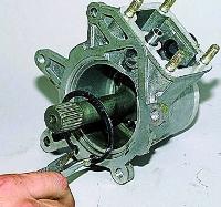
The device of the vacuum brake booster is shown in fig. 1.
The vacuum booster is quite complicated, it requires some skills and special equipment to repair it, so if the amplifier fails, replace it as an assembly.
The principle of operation of the vacuum brake booster
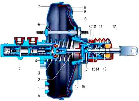
Vacuum booster: 1 - tip mounting flange; 2 - stock; 3 - diaphragm return spring; 4 - sealing ring of the flange of the main cylinder; 5 - main cylinder; 6 - amplifier pin; 7 - amplifier housing; 8 - diaphragm; 9 - amplifier housing cover; 10 - piston; 11 - protective cover of the valve body; 12 - pusher; 13 - pusher return spring; 14 - valve spring; 15 - valve; 16 - stock buffer; 17 - valve body; A - vacuum chamber; B - atmospheric chamber; С, D - channels
The rubber diaphragm 12, together with the valve body 24, divides the cavity of the vacuum booster into two chambers: vacuum A and atmospheric B.
Camera A is connected to the engine inlet pipe through the check valve of the tip 11 and a hose.
Plastic valve body 24.
At the exit from the cover, it is sealed with a corrugated protective cover 16.
In the valve body there is a rod 3 of the drive of the main cylinder with a support sleeve, a buffer 23 of the rod, a piston 15 of the valve body, a valve 21 as an assembly, return springs 19 and 20 of the pusher and valve, an air filter 17, a pusher 18.
When the pedal is pressed, the pusher 18 and the piston 15 move, followed by the valve 21 until it stops against the seat of the valve body.
At the same time, cameras A and B are separated.
As the piston moves further, its seat moves away from the valve and chamber B is connected to the atmosphere through the resulting gap.
Air entering through the filter 17, the gap between the piston and the valve and channel D, creates pressure on the diaphragm 12.
Due to the pressure difference in chambers A and B, the valve body moves together with stem 3, which acts on the master cylinder piston.
When the pedal is released, the valve 21 moves away from the seat of the body and communicates with each other through the resulting gap and channel C of chambers A and B.
Removal and installation
You will need: keys "for 10", "for 13", "for 17".
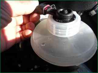
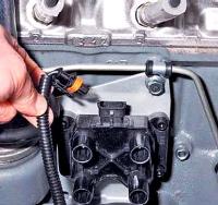
Disconnect the wiring harness from the brake fluid level sensor.
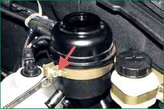
Remove the bolt of the power steering reservoir bracket
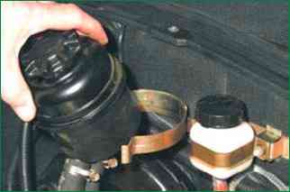
Remove the tank from the bracket and move it to the side.
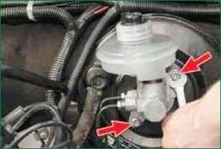
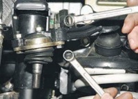
Remove the two nuts securing the brake master cylinder to the vacuum booster
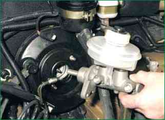
Without bending or twisting the brake pipes, carefully move the brake master cylinder to the side
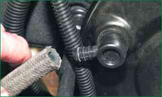
Hold the check valve and disconnect the hose from it
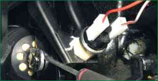
From inside the passenger compartment, remove the retaining clip from the brake pedal pin.
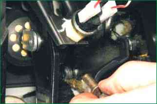
Remove the brake pedal pin, thereby disconnecting the push rod of the vacuum booster from the pedal
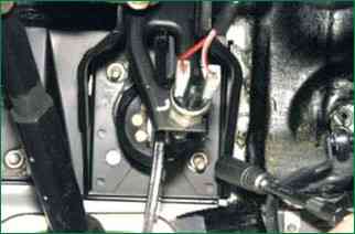
Remove the vacuum booster mounting nuts
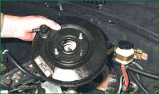
Remove the vacuum booster.
Install the vacuum booster in the reverse order of removal


