We prepare the car and disconnect the negative battery terminal
There is an emergency power supply in the circuit of the airbag system control unit
In order to discharge the capacitors, after turning off the ignition, wait at least 10 seconds before working.
Removing the driver's airbag module
We set the front wheels to the position of the rectilinear movement of the car. The upper spokes of the steering wheel must be in a horizontal position.
Open the left front door.
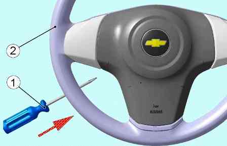
Being outside the car, on the side of the steering wheel, insert a flat-blade screwdriver 1 (Fig. 1) into the left hole on the steering wheel, press on the screwdriver, release the module from the steering wheel lock.
Turn the steering wheel 180 degrees and insert a flathead screwdriver into the right hole on the steering wheel.
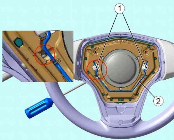
Press on the screwdriver to release the module from the latches 1 (Fig. 2) of the steering wheel.
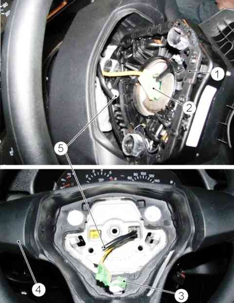
Return the steering wheel to its original position, remove the module 1 (Fig. 3) of the airbag without putting tension on the L-shaped block harness.
Using a flat screwdriver, disconnect the latch 3 and disconnect the L-shaped block 2 from the module, disconnect the block 5 of the sound signal, remove the gas generator module 1.
Attention. Place the failed gas generator module on a flat surface with the facing cover up.
When melting the L-shaped block in case of dismantling the triggered gas generator module, disconnect the module by cutting the block harness.
Installing the driver's airbag
Before installing the gas generator module, visually check for mechanical damage and the presence of a label with a barcode and identification number on the gas generator module.
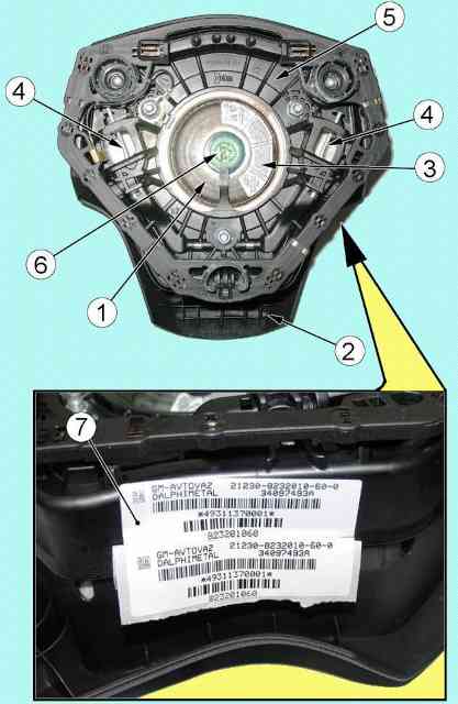
Attention. When installing a new gas generator module, tear off label 7 (Fig. 4) with a barcode from the gas generator module and paste it into the "Special Marks" section of the service book, indicating the date of installation and vehicle mileage, the reason for replacement.
From the outside of the car to the side of the steering wheel, bring the gas generator module to the installation site in the steering wheel, attach the horn pads, without applying lateral force, insert the L-shaped block into the gas generator module connector until a characteristic locking click is obtained.
Insert the latch into the block until it clicks.
Attention. Before installing the latch in the L-shaped block, the airbag module is in the transport position, the contacts of the igniter connector are shunted.
Move the gas generator module to the steering wheel socket, then insert the airbag module until it clicks into the steering wheel.
Removing connector with rotating device
Remove the driver's airbag as described above
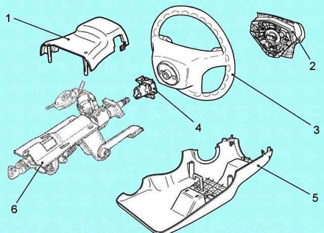
Unscrew the fastening screws and remove the casing 1 (Fig. 5) facing the top and casing 5 facing the bottom.
Remove the O-ring from the ignition switch.
Set the front wheels to straight ahead. The upper spokes of the steering wheel must be in a horizontal position.
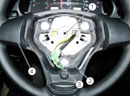
Unscrew the nut 1 (Fig. 6) securing the steering wheel and remove the steering wheel 4 from the steering shaft, while passing the blocks 2 and 3 of the wiring harness through the hole in the steering wheel hub.
Attention. After removing the steering wheel, exclude axial movement of the cylindrical lock. To avoid breakage, do not rotate the cover of the rotating device, as it is automatically fixed.
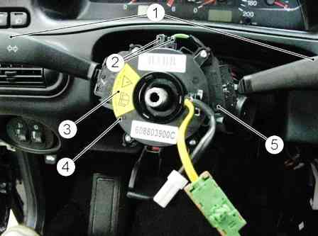
Remove the switches 1 (Fig. 7) of the wipers and light signaling from the connector.
Disconnect the pads 2 of the instrument panel harness from the connector.
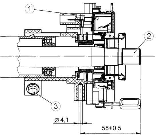
Loosen the bolt 3 (Fig. 8) of the fastening and remove the connector with the rotating device assembly from the steering shaft.
Installing a connector with a rotating device
Attention. The installation of the connector with the device rotating on the steering shaft must be carried out immediately before installing the steering wheel on the shaft.
Before installation, the bipod of the steering mechanism must be in the middle position, while the front wheels must be in the position of the rectilinear movement of the vehicle.
Install connector 1 (Fig. 8) with a rotating device on the steering shaft, do not tighten bolt 3 of the connector.
Attention. If an unintentional rotation of the cover of the rotating device has occurred, it is necessary to set it to the middle position.
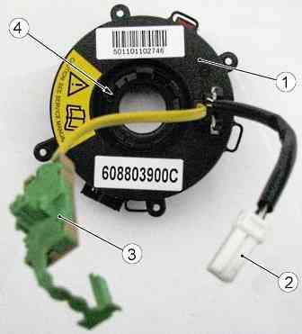
To do this, press the cylindrical latch 4 (Fig. 9) and, carefully turning it to the left or right until a noticeable resistance, bring the cover 1 of the rotating device to its extreme position.
Then turn cover 1 two full turns in the opposite direction and on the third turn set it in position as shown in figure 7 (label 3 should be on the left, wiring harness terminals on the right).
Release the cylindrical lock until the lid locks into place.
When installing a new connector with a rotating device, remove the red transport lock from the rotating device, which fixes the moving element of the device in the middle position, turn the transport lock around its axis by 150°+30°.

Move the connector 1 (Fig. 10) with the device rotating as an assembly along the axis of the shaft so that the control dimension from the end of the shaft 2 to the axis of the screw for fastening the lower facing casing to the connector is 58 + 0.5 mm. Install and tighten bolt 3.
Connect the instrument panel harness connectors to the connector.
Attention. Before installing the steering wheel on the steering shaft, make sure that the front wheels are The vehicles are in the direction of rectilinear movement.

Pass blocks 2 and 3 (Fig. 11) of the rotating device into the right hole of the steering wheel hub and install steering wheel 4 on the steering shaft. At the same time, the upper spokes of the steering wheel must be in a horizontal position.
Fasten and tighten the steering wheel nut 1 observing the tightening torque of 31.4-51 Nm (3.2-5.2 kg.m).
Install the wiper and light switches in the connector.
Install the O-ring on the ignition switch.
Install the upper and lower claddings and secure them with screws.
Turning the steering wheel to the right and to the left until it stops, make sure that there are no jams, knocks and smooth rotation, as well as the operability of resetting the turn signal lever.
While swinging the steering wheel, make sure that there are no radial and axial play of the steering wheel.
Install the driver's airbag module
Removing the airbag control unit
Remove the instrument panel as described in the article - How to remove the VAZ-2123 instrument panel from 2009
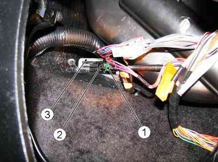
Move the latch 1 (Fig. 12) of the block to the side and disconnect the block 2 of the instrument panel wiring harness from the connector of the control unit 3 of the airbag control.
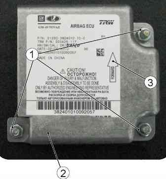
Unscrew the nuts 1 (Fig. 13) fastening the control unit 2 of the airbag control and remove the control unit.
Installing the airbag control unit
Install the control unit in the reverse order of removal.
When installing the BUSNPB, the arrow 3 on the block cover must be directed in the direction of the vehicle.
Attention. The SNPB control unit is delivered to the spare parts in a blocked state. After replacing the control unit, it must be unlocked.
Removing the passenger airbag module
Remove the instrument panel glove box.
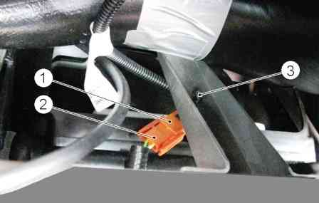
Disconnect block 1 (Fig. 14) of the auxiliary wiring harness from block 2 of the instrument panel wiring harness. Detach the bracket 3.
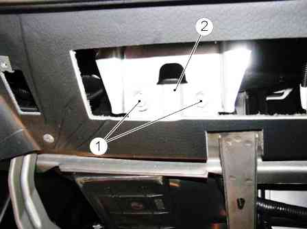
Unscrew bolts 1 (Fig. 15) fastening the module to bracket 2 of the instrument panel cross member.
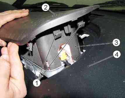
Through the opening of the glove box, alternately acting on the latches 1 (Fig. 16) of the facing cover 2 of the MUABP, feeding from below, remove the UABP module 3 from the instrument panel 4.
Attention. Put the airbag module that did not work on a flat surface with the facing cover up.
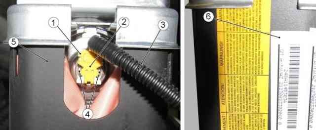
Using a flat screwdriver, remove latch 2 from the L-shaped block 1 (Fig. 17) attached to the MNPBP connector, then, using a thin flat screwdriver, press the fixing antennae 4 of the block and disconnect the L-shaped block 1 from the module connector 5 and remove the harness 3 wires optional.
In case of dismantling a triggered airbag module, check the wiring harness to the airbag module.
If there is damage to the block to the airbag module, melting, breakage or short circuit of the wires to the airbag module, replace the harness.
Installing the passenger airbag module
Before installing the MNPBP, visually check that there are no mechanical damages and that there is a label with a barcode and an identifying number on the module.
Attention. When installing a new airbag module, tear off label 6 (Fig. 17) with a barcode from the module and paste it into the "Special marks" section of the service book, indicating the date of installation and vehicle mileage, the reason for replacement.
Insert the L-shaped block of the wiring harness of the additional instrument panel into the connector of the airbag module until you hear a distinctive locking click.
Insert the latch into the L-shaped block until it clicks.
Attention. Before installing the latch in the L-shaped block, the airbag module is in the transport position, the contacts of the igniter connector are shunted.
Install the airbag module in the instrument panel and fix the cover of the airbag in the instrument panel.
Fasten and tighten the bolts securing the MAPBP to the bracket, observing the tightening torque (8 + 1) Nm, while ensuring a uniform gap between the MAPBP cover and the instrument panel.
Connect the additional harness to the instrument panel harness, install the instrument panel glovebox.
Removing the pretensioner
Pull the seat shift lever and slide the front seat back.
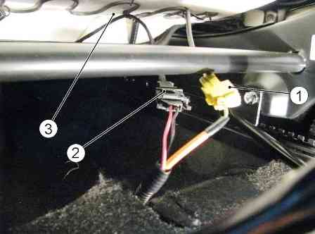
Disconnect connector 1 (fig. 18) of the front seat belt pretensioner harness.
Disconnect connector 2 of the seat heating harness (if equipped).
Remove the front seat
Attention. Work on the removal / installation of the seat belt pretensioner must be carried out with gloves.
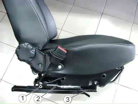
Unscrew the bolt 1 (fig. 19) fastening the seat belt pretensioner, and carefully holding the pyrotechnic tube, disconnect the seat belt pretensioner 2 with the spacer from the front seat sled 3.
Installing the seat belt pretensioner
Before installing the seat belt pretensioner, visually inspect for mechanical damage.
Install the front seat belt pretensioner with spacer on the front seat sled, install and tighten the pretensioner mounting bolt.
Install the seat in the car in the reverse order of removal.
Connect the front seat belt pretensioner harness connector to the rear harness connector.
Connect the seat heating harness connector (if equipped) to the rear harness connector
After completing the removal / installation of the components of the airbag, connect the terminal of the "ground" wire to the battery.
Attention. The ignition must be switched off when connecting the ground wire terminal to the battery. In this case, no one should be in the car.


