The EVAP system consists of a carbon adsorber with a purge solenoid valve and connecting pipelines
Gasoline vapors from the fuel tank are fed into a trap vessel (activated charcoal adsorber) to hold them when the engine is not running.
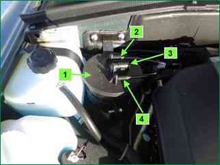
Vapours enter through the nozzle marked "TANK" (Fig. 1)
The controller, by controlling the solenoid valve, purges the canister after the engine has been running for a specified period of time from the moment the transition to the closed loop fuel control mode.
Air is supplied to the adsorber through the "AIR" branch pipe, where it is mixed with gasoline vapors. The resulting mixture is sucked into the intake pipe of the engine for combustion during the working process.
The controller regulates the degree of purge of the adsorber depending on the engine operating mode, applying a signal to the valve with a variable pulse frequency (16 Hz, 32 Hz).
The controller constantly monitors the influence of the purge (the state of filling the adsorber with fuel vapors) on the operation of the engine according to the information of the signal from the UDC.
If the adsorber has a high % filling with fuel vapors, the controller reduces the fuel supply (the factor characterizing the degree of filling with fuel vapors FU-COTE_W is about 2%, respectively, if the % filling with fuel vapors is low - FU-COTE_W is about 0%).
The controller checks the condition of the canister purge valve on each trip with a warm engine, completely closing it and opening it to a value exceeding the value set for this engine operation mode.
Based on the deviation of the fuel supply correction factor, the controller determines the state of the canister purge valve.
The scan tool displays the duty cycle of the control signal. A coefficient of 0% means that the adsorber is not purged. A factor of 100% means that maximum blowdown occurs.
The controller turns on the purge solenoid valve when:
- - coolant temperature is above a certain value;
- - the system works in feedback mode on the oxygen sensor signal;
- - the system is working.
Faults and their causes
Idle instability, engine stall, increased toxicity and deterioration in driving performance can be caused by the following reasons:
- - purge solenoid valve failure;
- - adsorber damage;
- - adsorber overflow;
- - damaged or incorrect hose connections;
- - pinched or clogged hoses.
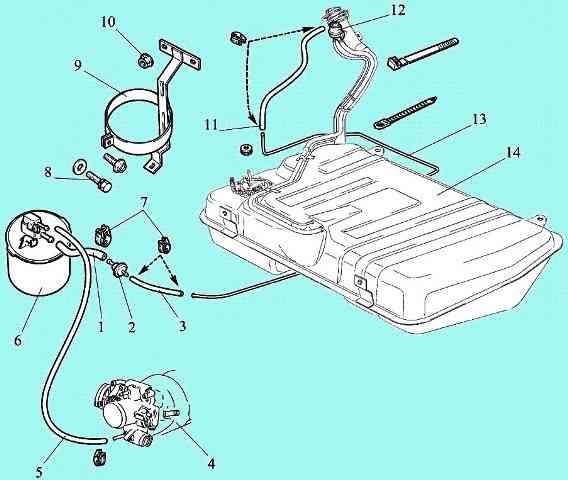
Euro-2 gasoline vapor recovery system: 1 - adsorber hose and gas tank valve; 2 - fuel tank valve; 3 - gas tank valve hose of the steam pipeline; 4 - throttle pipe with a receiver; 5 - adsorber hose and throttle pipe; 6 - adsorber; 7 - clamp; 8 - bolt; 9 - adsorber mounting bracket; 10 - nut; 11- steam pipeline and gravity valve hose; 12 - gravity valve; 13 - steam pipe; 14 - fuel tank.
Scheme of EURO-2 gasoline vapor recovery system and EURO-3 gasoline vapor recovery system
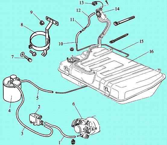
Euro-3 gasoline vapor recovery system: 1 - throttle pipe and adsorber purge valve hose; 2 - solenoid valve for adsorber purge; 3 - purge valve and adsorber hose; 4 - adsorber; 5 - steam pipe hose; 6 - throttle branch pipe with a receiver; 7 - bolt; 8 - adsorber mounting bracket; 9 - nut; 10 - steam line hose and adapter; 11 - adapter; 12 - hose adapter and gravity valve; 13 - gas tank cap with safety valve; 14 - gravity valve; 15 - steam pipe; 16 - fuel tank
The EURO-4 toxicity reduction system differs from the EURO-3 toxicity reduction system by the original converter.
To comply with Euro-5 standards, an additional silencer 21230-1200018-50 with a converter 21230-1206026-50 is used
Visual control of the canister and canister purge valve
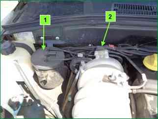
Inspect the solenoid valve and adsorber (fig. 2). If there are cracks or damage to the body, replace the assembly.
Check the reliability of the connection of the vacuum and vapor supply hoses from the gas tank.
Removing the canister purge solenoid valve
Preparing the car and removing the engine screen
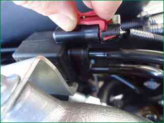
Disconnect the block from the adsorber purge valve by depressing the block latches
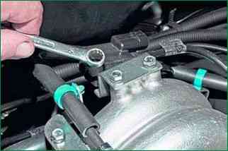
Using a 10 key, unscrew the two bolts securing the valve bracket to the intake manifold receiver
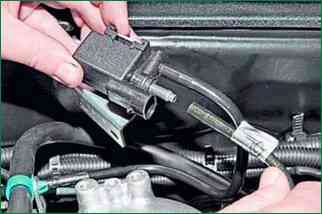
We remove the valve with the bracket from the receiver and disconnect the tubes connecting it to the throttle assembly from the valve fittings
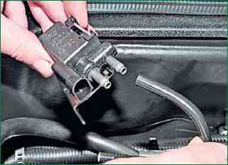
Disconnect the tube connecting to the adsorber
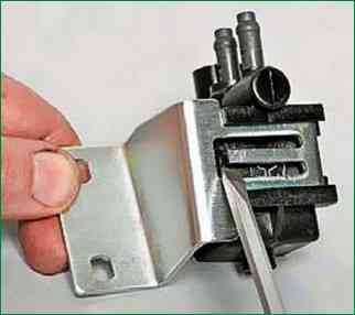
Pry off the bracket retainer with a flat screwdriver
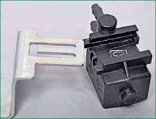
We move the bracket along the valve guides and separate them
Removing the adsorber
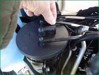
Disconnect the tubes from the adsorber fittings connecting to the purge valve and the gravity valve
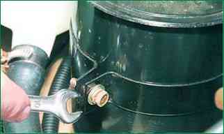
Using a 10 key, we loosen the tightening bolt of the adsorber bracket and remove the adsorber from the bracket
Install the elements of the vapor recovery system in reverse order


