")
")
")
")
")
")
The heating (air conditioning) and ventilation system is a single complex that provides the most comfortable conditions in the car interior, regardless of weather conditions and driving conditions
The system includes a heater (increases the air temperature in all operating modes of the system), an air conditioner (reduces the temperature and humidity of the air, is set depending on the vehicle configuration), an air blower, air ducts with a filter (provide air exchange in the cabin, purify the air from dust ) and a control unit (controls all elements of the system to obtain the specified comfort parameters).
The car is equipped with a liquid-type interior heater.
The heater radiator is connected to the engine cooling system by two hoses running in the engine compartment.
The radiator is placed in a plastic casing of the climate unit, installed under the central part of the instrument panel.
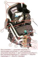
The main components of the heater:
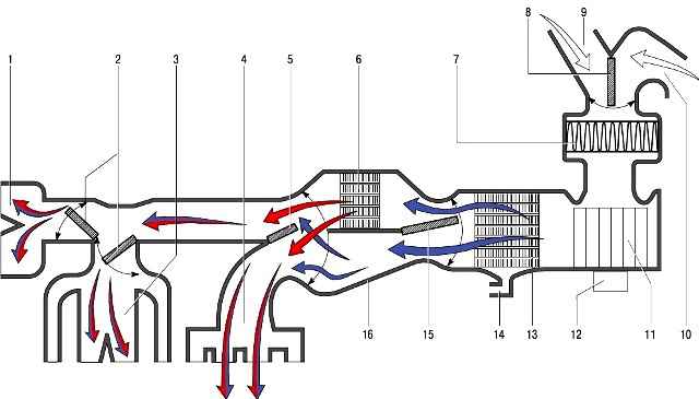
- - radiator 6 of the heater, designed to heat the air entering the cabin with the heat of the engine cooling fluid;
- - blower 11.
Air blower motor 12 with permanent magnet excitation provides a controlled supply of outside air to the heater and air conditioning dampers.
In order to obtain different values of the speed of the air blower, a block of additional resistors is installed in the power supply circuit of the electric motor;
- - damper 15 for the temperature regulator of the air coming from the heater to the passenger compartment. The change in its position determines the amount of air passing through the heater core and outside air passing around the heater core;
- - dampers 2 for distributing air from the heater through air ducts to the passenger compartment or for blowing the windshield.
Construction of the air conditioning system
In a variant, a compressor-type air conditioning system is installed on the car
The units of the heater and the evaporator of the air conditioner are arranged in one block.
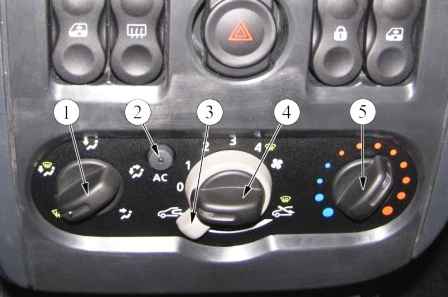
The controls for the air conditioning system are located in a block shared with the controls for the heater.
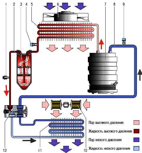
A schematic diagram of the movement of the refrigerant in the air conditioning system is shown in the figure.
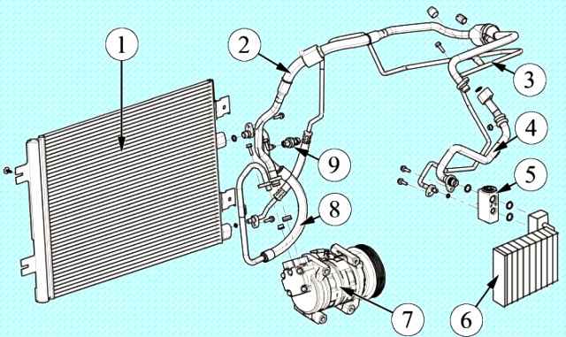
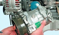
The compressor is mounted on the engine block and is driven by a ribbed belt.
The compressor circulates the refrigerant in the system.
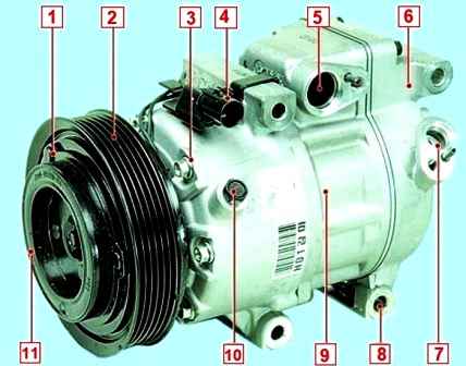
The compressor shaft is installed in the aluminum front housing cover on bearings and sealed on the side of the drive pulley with an oil seal.
Compressor drive pulley 2 is mounted on a double-row ball bearing and constantly rotates when the engine is running.
When the air conditioner is turned on, torque is transmitted from the pulley to the compressor rotor through a friction clutch with an electromagnetic drive.
If the system is in good order, when the air conditioner is turned on, a click is heard - this is the clutch pressure disk 1, under the action of an electromagnet, engages with the drive pulley 2, and the compressor rotor starts to rotate.
But during the operation of the air conditioner, the following compressor malfunctions may occur.
If, when the air conditioner is turned off, the clutch makes extraneous sounds during rotation, heats up, or a burning smell appears, then its bearing has probably begun to collapse. In this case, the bearing must be replaced.
In some advanced cases, it may be necessary to replace the compressor clutch assembly or its components.
If you don't hear a click after turning on the air conditioner, then the following problems may occur:
- – a refrigerant leak has occurred and the control system is blocking the compressor from turning on;
- – the pressure sensor in the system has failed;
- - malfunctions in the electrical circuits of the control system;
- - the coil winding of the clutch electromagnet burned out;
- - the engine control unit for some reason (high engine coolant temperature, high engine speed) has blocked the compressor from turning on.
If the clutch rotates easily and freely, but when the air conditioner is turned on, extraneous noises are clearly audible or the engine even stalls, then the compressor is most likely stuck.
The internal pumping part of the compressor cannot be repaired. In this case, the compressor will have to be replaced.
And the last, most unpleasant option.
A click is heard, the clutch easily rotates the compressor shaft, and the air in the cabin is not cooled. In this case, the compressor runs idle, pumping nothing.
Only an experienced specialist with special monitoring and diagnostic equipment can determine this malfunction.
The cause of the malfunction can be most accurately determined after a complete diagnosis at a specialized service center for the repair of automotive air conditioners.
A condenser (air conditioner radiator) of a multi-flow type is located in front of the radiator of the engine cooling system.
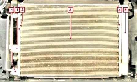
It is attached with four brackets to the radiator frame.
The condenser cells are made of flat thin-walled aluminum tubes with internal longitudinal baffles for rigidity and external fins to improve heat transfer.
Aluminum tanks, with flanges for connecting pipelines and a receiver. The tanks are divided into sections by height, therefore, passing through the condenser, the refrigerant flow changes direction several times.
In the condenser, the vapors of the refrigerant compressed by the compressor condense and the heat released during this is removed into the surrounding air.
When the air conditioner is turned on, the engine control unit turns on the power supply circuit for the electric fan of the engine cooling radiator, which improves heat transfer in the condenser and reduces pressure in the air conditioner system.

At least once a year, preferably before the start of summer operation, wash the fins "A" of the condenser cells from adhering dirt, dust and anti-icing agents "B". This will improve heat transfer, reduce pressure in the system and increase the service life of the system elements.
Do not use high pressure water jets to clean the condenser. This may cause damage to the "B" thin-walled fins.
Even with regular washing, the need to replace the condenser occurs much more often than we would like.
The fact is that he is the first to take on the flow of anti-icing reagents, dirt and pebbles from the road. And the walls of the tubes are thin.
In most cases, the condenser is damaged by corrosion in the third or fourth year of operation.
If the tightness of the condenser is broken as a result of corrosion, then it is more expensive to repair it.
Even if the argon welder succeeds in patching the hole, a leak may soon appear elsewhere. By the way, the pressure in the system on hot days can reach up to 25–28 bar.
In addition, the complex structure of the condenser tube should be taken into account: along it is divided into channels by partitions, so it is likely that after welding, some of the channels will be blocked.
Accordingly, the dissipated power will drop and the operation of the air conditioner will deteriorate, especially in traffic jams and in hot weather.
After each experiment with condenser patching, you will need to pay for removal-installation, welding of the condenser and charging the system with refrigerant. So it's better to install a new condenser right away.
The evaporator is located in the block of the heating (air conditioning) and air ventilation system in the cabin.
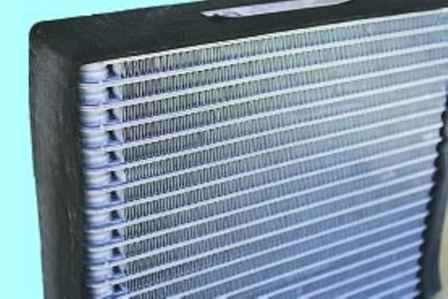
The evaporator is made of aluminum tubes with external fins to improve heat transfer.
Passing through the evaporator tubes, the boiling refrigerant actively absorbs heat from the air blowing over the outer finned surface of the tubes. The air is cooled and the air blower is supplied to the passenger compartment.
When the air passing through the evaporator cools, the water vapor contained in it condenses.
The condensate drains through the drain pipe located on the lower part of the right side of the body panel, under the bottom of the car.
If the ambient humidity is high, a puddle of water may form under the car, which is an indirect sign of the health of the air conditioning system.
During the operation of the car, particles of road dust and dirt settle on the outer surface of the evaporator that is wet from condensate.
This layer becomes an excellent environment for life and rapid reproduction of putrefactive bacteria and fungal cultures.
Over time, an unpleasant smell develops in the car. It is especially strong when the air conditioner is turned off and in humid weather.
In order to minimize the risk of this problem, when buying a new car, it is necessary to carry out preventive treatment of the evaporator with special chemicals, regularly replace the cabin filter and clean the drain tube.
On the side surface of the evaporator there is a flange for mounting a thermostatic valve.
The thermostatic expansion valve is a block type located in the evaporator body.
The valve is attached to the pipelines and the evaporator using flange connections.
After passing through the throttling hole in the valve body, the liquid refrigerant abruptly reduces its pressure and begins to boil.
A control element is installed in the valve body, which changes the flow area of the throttling hole depending on the pressure and temperature of the refrigerant.
The control element is set at the factory and cannot be adjusted during operation.
The receiver-drier is installed on the condenser on the left side and forms a non-separable unit with it.
Inside the housing there is a filter element (cartridge) filled with desiccant (silica gel) granules.
The liquefied refrigerant passing through the receiver is cleaned of possible impurities, dirt and moisture. In the lower part of the housing there is a hole for replacing the filter element.
In case of repair or replacement of elements of the air conditioning system, if it was in an open state (any components were removed, pipelines were destroyed, etc.), the cartridge of the receiver-drier must be replaced.
Otherwise, after charging the system, the refrigerant will not be drained and inside the system there may be images There are acids that will destroy the parts of the air conditioner from the inside.
Pipes connect all elements of the air conditioning system into a single sealed circuit.
Pipelines and their fastening flanges are made of aluminum alloys.
Protect metal sections of pipelines from dents and kinks. Any narrowing of the flow area of the pipeline leads to a decrease in system performance.
In order to connect the mutually moving elements of the system, pipelines in some sections are equipped with flexible inserts made of synthetic materials.
O-rings made of neoprene are installed at the junctions of the individual elements of the system.
During the repair of the system, when disconnecting sections of pipelines, sealing rings must be replaced. Tighten threaded connections of pipelines to the recommended torque.
Too tight or too tight will cause sealing surfaces to warp and refrigerant to leak.
Service valves for connecting diagnostic and filling equipment are located on pipelines.
The valves are equipped with spools, similar in design to wheel spools, but different in size.
A special key is used to turn the spools in and out.
It is forbidden to check the presence of refrigerant in the system by pressing the spools of the service valves, since after such a check the valve spool may not close completely and the refrigerant will leak from the system!
The pressure sensor is installed on the pipeline section of the high pressure line.
According to the signals of the sensor, the electronic engine control unit turns off the air conditioning compressor in case of depressurization of the system or an emergency increase in pressure in it in order to protect the compressor from overloads.
The control unit for the heating, air conditioning and ventilation system is installed in the instrument panel.
Refrigerant
The system is charged with HFC-134a (R-134a) refrigerant. The total filling volume is (450±25) g.
Special oil FD 46XG (PAG) has been added to the refrigerant to lubricate the compressor. It is strictly forbidden to use other types of refrigerants and oils in the system.
During the operation of a car air conditioner, situations periodically arise when maintenance of the air conditioning system or its repair is required. For this, modern diagnostic and repair equipment is used.
The most common situation is the depressurization of the system and the release of refrigerant from it.
Highly sensitive halogen leak detectors with audible indication are used to detect leaks.
In some difficult cases, the method of the so-called ultraviolet diagnostics of the tightness of the air conditioning system is used.
The method consists in introducing a special dye into the system in microdoses. In places of microflows, the dye, together with the refrigerant, gradually comes to the outer surface of the system elements.
During the inspection of the system, the dye under the influence of ultraviolet rays of a special lamp begins to glow (fluoresce) and the refrigerant leaks become visible.
It should be noted that the dye does not have any negative effect on the system.
It can sit in the refrigerant and circulate through the system for as long as you want, and serve its purpose only when a leak occurs.
After repairing the air conditioner, it is necessary to evacuate and charge the system with the appropriate refrigerant (R-134a). The volume of air conditioning refueling for each car model is individual.
To carry out high-quality refueling of a car air conditioner, you need:
- - precision manometric blocks with special connecting tips;
- – two-stage vacuum pump for complete removal of air and water vapor from the system;
- – high-precision (division not more than 5 g) scales for dosing the refrigerant charged.
Due to the specifics of repairing the air conditioning system, this section describes only the removal and installation of individual elements and the system control unit.
Work related to charging the system with refrigerant should be carried out at specialized service centers.
The air conditioning system is charged with high pressure refrigerant.
The ingress of liquid refrigerant on human skin causes severe frostbite, so all work related to the maintenance, repair or dismantling of air conditioning system elements should be carried out, if possible, in specialized service centers equipped with professional technological equipment.
Take precautions when working on your own.
Ventilation system device
The vehicle has a supply and exhaust type ventilation system.
Outside air can enter the passenger compartment through the door windows when lowering these windows and through the air blower grill located in front of the windshield.

The air from the air blower is supplied through the air ducts to the vehicle interior through the windshield blowing nozzles, side and central nozzles, as well as through the lower nozzles of the heater housing.
Exhaust ventilation is carried out through the grill, which is installed in the trunk of the car
When placing cargo in the trunk, if possible, try not to block the ventilation grille. Leave a small gap between luggage and trim panels.
Efficient exhaust ventilation improves the temperature in the cabin and reduces the formation of condensation on the windows.

From the outside, the exhaust ventilation openings are closed by deflectors with petal flaps, which are installed in the rear part of the body, in the cavity of the rear bumper.
Safety when servicing the air conditioning system
Refrigerant is a chemical compound that must be handled with care to avoid harm to health.
Work in a well-ventilated area and avoid breathing refrigerant vapors.
When performing work related to the depressurization of the air conditioning system, always wear safety goggles and wrap fittings, valves and connections with a clean cloth.
It is forbidden to carry out welding work on the car near the components and pipelines of the air conditioning system.
It is forbidden to bend flexible pipe fittings (hoses) with a radius less than four flexible connector diameters.
Regularly inspect the hoses for cracks and abrasions.
All refrigerant must be removed from the air conditioning system before disconnecting the pipes.
Unscrew the threaded connections of the system elements slowly.
Keep your face and hands away from the disconnect to avoid injury if there is liquid refrigerant in the system.
If pressure is detected in the system when the pipes are disconnected, remove the refrigerant from the system.
Immediately after disconnecting any part of the system, close the holes with caps or tape.
This will prevent moisture and dirt from entering the system, which can cause compressor pump failure.