We prepare the car for repair and install it on a lift or on a viewing ditch

If the car is on a viewing ditch, then block the front wheels and substitute wheel chocks
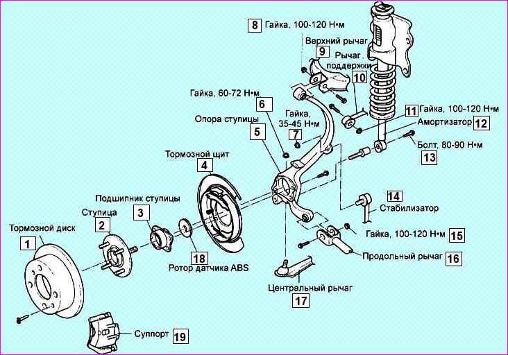
Rear suspension parts: 1 - brake disc; 2 - hub; 3 - hub bearing; 4 - brake shield; 5 - hub support; 6, 7, 8,11,15 - nut; 9 - upper lever; 10 - support lever; 12 - shock absorber; 13 - bolt; 14 - stabilizer; 16 - trailing arm; 17 - central lever; 18 - ABS sensor rotor; 19 - caliper

Loosen the rear wheel nuts on the side of the work being performed
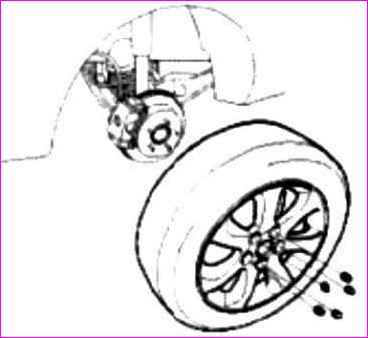
Removal and repair of the hub and trunnion of the rear axle of Kia Magentis and Optima

Release the parking brake and remove the rear wheel

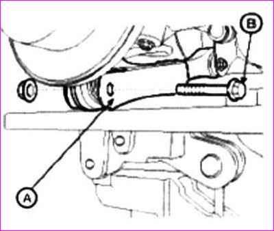
We place a jack under the lower rear suspension arm (A), then raise it, as shown in the figure above, to load the suspension
Removal and repair of the hub and trunnion of the rear axle of Kia Magentis and Optima

Unscrew the bolt (B) of the lever (A). Bolt tightening torque 140-160 Nm
Removal and repair of the hub and trunnion of the rear axle of Kia Magentis and Optima

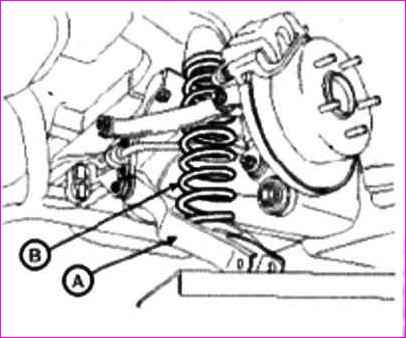
Unscrew the nut securing the cross member and the rear lower arm (A)

Then remove the suspension spring (B) by lowering the jack as shown. Nut tightening torque 140-160 Nm
Removal and repair of the hub and trunnion of the rear axle of Kia Magentis and Optima

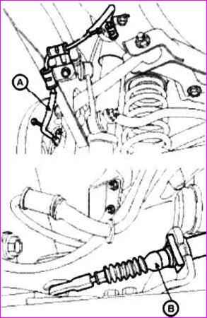
Disconnect the rear wheel speed sensor (A) and the parking brake cable (B)
Removal and repair of the hub and trunnion of the rear axle of Kia Magentis and Optima

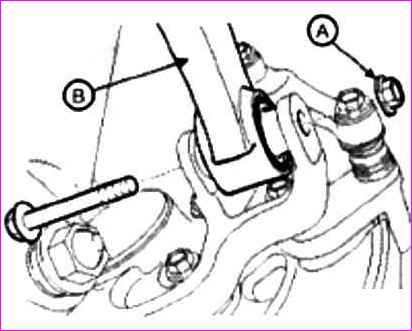
We unscrew the mounting nut (A), remove the bolt and disconnect the upper suspension arm (B) from the trunnion. Nut tightening torque 100-120 Nm
Removal and repair of the hub and trunnion of the rear axle of Kia Magentis and Optima

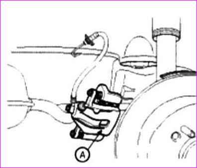
Unscrew the brake caliper mounting bolts (A). Bolt tightening torque 60 Nm
Removal and repair of the hub and trunnion of the rear axle of Kia Magentis and Optima

Remove the caliper and hang it by the body elements
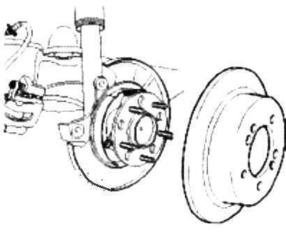
Removal and repair of the hub and trunnion of the rear axle of Kia Magentis and Optima

Unscrew the fastening screws and remove the brake disc
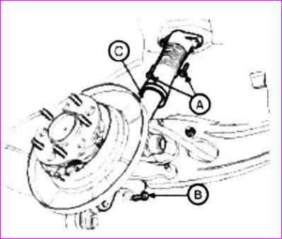
Removal and repair of the hub and trunnion of the rear axle of Kia Magentis and Optima

Unscrew the upper and lower mounting bolts (A, B) of the shock absorber (C).

Bolt tightening torque:

  • - bolt (A) - 45-55 Nm;
  • - bolt (B) - 140-160 Nm

Remove shock absorber
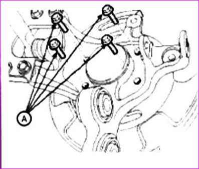
Removal and repair of the hub and trunnion of the rear axle of Kia Magentis and Optima

Removed repair and repair of the hub and trunnion of the rear axle of Kia Magentis and Optima

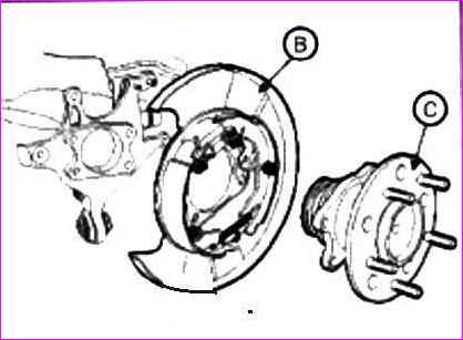
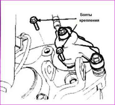
We unscrew the mounting bolts (A) of the hub and remove the hub assembly and the rear brake

Remove the cotter pin and unscrew the castellated nut securing the additional suspension arm.

Nut tightening torque 40-45 Nm
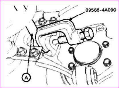
Removal and repair of the hub and trunnion of the rear axle of Kia Magentis and Optima

Using the tool (09568-4A000), disconnect the auxiliary lever (A) from the support.

Tightening torque of the bolts 45-55 Nm
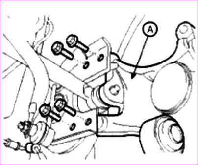
Removal and repair of the hub and trunnion of the rear axle of Kia Magentis and Optima

We unscrew the bolts and remove the support assembly (A) from the trailing arm. Bolt tightening torque 45-55 Nm.

Replacing the hub bearing and hub support bushings

Disconnecting the parking brake

Remove the wheel

Remove the wheel speed sensor

Remove the caliper and fix it on the rear suspension strut
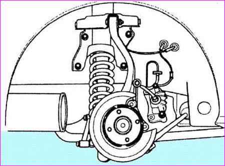
Removal and repair of the hub and trunnion of the rear axle of Kia Magentis and Optima

Remove the brake disc

Removal and repair of the hub and trunnion of the rear axle of Kia Magentis and Optima

We unscrew the four bolts securing the hub to the hub support
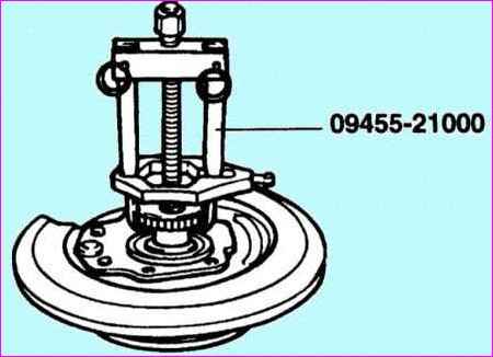
Removal and repair of the hub and trunnion of the rear axle of Kia Magentis and Optima

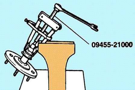
Using a puller, remove the ABS sensor rotor
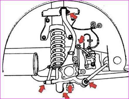
Removal and repair of the hub and trunnion of the rear axle of Kia Magentis and Optima

Remove the hub support

Removal and repair of the hub and trunnion of the rear axle of Kia Magentis and Optima

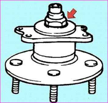
Bend off the shoulder and unscrew the nut of the rear wheel hub
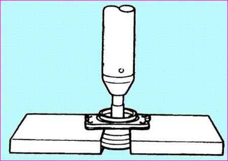
Removal and repair of the hub and trunnion of the rear axle of Kia Magentis and Optima

We press out the rear axle bushing

Removal and repair of the hub and trunnion of the rear axle of Kia Magentis and Optima

Using a puller, press the inner race of the bearing out of the hub
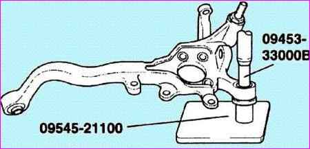
Removing and repairing the hub and trunnion of the rear axle of Kia Magentis and Optima

We press out and press in two bushings of the hub support
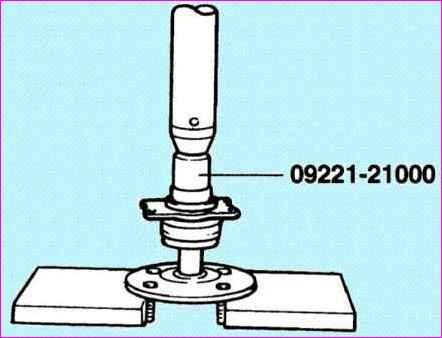
Removal and repair of the hub and trunnion of the rear axle of Kia Magentis and Optima

We apply a thin layer of engine oil and, using a suitable mandrel, press the bearing in, applying force to the inner race
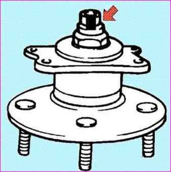
Removing and repairing the hub and trunnion of the rear axle of Kia Magentis and Optima

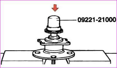
Tighten the new nut and drive the collar of the nut into the groove of the hub
Removal and repair of the hub and trunnion of the rear axle of Kia Magentis and Optima

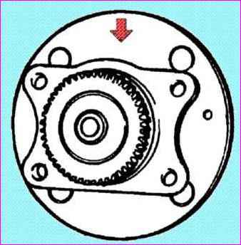
Using a suitable mandrel, we press in the ABS sensor rotor
Removing and repairing the hub and trunnion of the rear axle of Kia Magentis and Optima

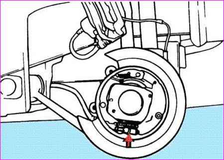
Mount the hub and bearing on the brake shield so that the rounded part of the outer ring of the bearing is pointing up
Removing and repairing the hub and trunnion of the rear axle of Kia Magentis and Optima

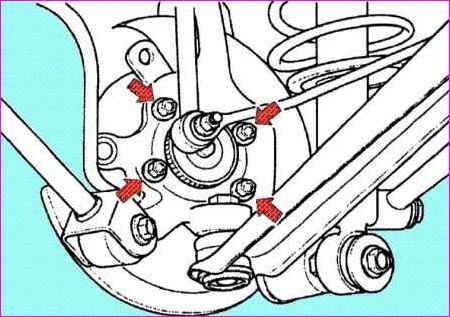
If installation is difficult, turn the parking brake adjusting nut to increase the distance between the brake pads and the mechanism
Removal and repair of the hub and trunnion of the rear axle of Kia Magentis and Optima

Tighten the four hub bolts

Installing the brake disc

Installing the caliper

Turn the hub several times so that the bearing elements are in place
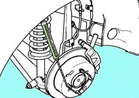
Removal and repair of the hub and trunnion of the rear axle of Kia Magentis and Optima

We measure the torque that must be applied to rotate the bearing

Torque: 2.8 Nm
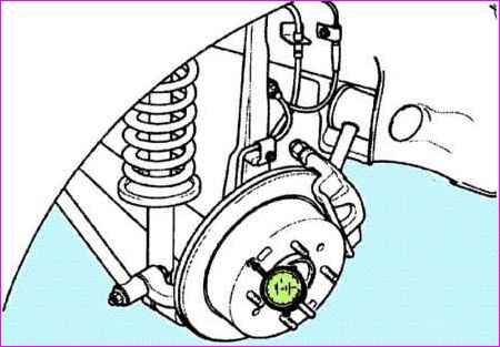
Removal and repair of the hub and trunnion of the rear axle of Kia Magentis and Optima

The criterion for determining whether the axial play of the hub is within precisely defined limits is absent

Bearing end play: 0.008 mm

Installing the wheel speed sensor

Install and adjust the parking brake.

New

Installing the intake camshaft of the front head of the Toyota Camry block

 Installing the intake camshaft of the front head of the block Installing the intake camshaft of the front head of the engine block 1AZ-FE

Apply a coat of engine oil to the end thrust surfaces of the camshaft

Scheme of the COURT ZMZ-405 with DMRV HFM-4.7 0280218037 "BOSCH" (Germany)

Schemes of ZMZ-405 engine control systems may differ depending on which mass air flow sensor is installed

Select your language