The VAZ-2123 engine was developed on the basis of the VAZ-21214 engine, which, in turn, is a modernized VAZ-21213 engine and complies with Euro II toxicity standards
The main difference between these engines and their predecessors is in the design of the gas distribution mechanism - a single-row chain and a hydraulic chain tensioner are used to reduce noise.
For the same purpose, hydraulic valve supports are installed, an additional difference is a boss on the cylinder block for installing a knock sensor.
The VAZ-21213 engine was equipped with a central injection system that did not have a knock suppression function.
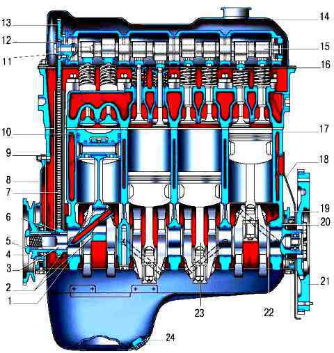
Fig. 1. Longitudinal section of the engine: 1 - main bearing shell; 2 - connecting rod bearing insert; 3 - crankshaft; 4 - crankshaft pulley; 5 - pulley fastening nut; 6 - crankshaft sprocket; 7 - timing chain drive; 9 - cover of the gas distribution mechanism drive; 9 - cover gasket; 10 - piston; 11 - thrust washer; 12 - lock washer; 13 - camshaft sprocket; 14 - cylinder head cover; 15 - camshaft; 16 - cylinder head cover gasket; 17 - cylinder block; 19 - clutch housing cover; 19 - holder of the rear oil seal; 20 - external thrust half ring of the crankshaft; 21 - flywheel; 22 - inner thrust half ring of the crankshaft; 23 - connecting rod; 24 - oil drain plug
The VAZ-2123 engine has an almost similar design to the VAZ-21214 engine of the Niva VAZ-21214 car.
The main difference is in the shape of the intake tract and in the location of the front supports of the power unit - for the VAZ-2123 engine, they are installed exactly on the center of gravity line, in contrast to the previous engines mounted on cantilever supports.
The engine cylinders are numbered starting from the crankshaft pulley.
On the left side of the cylinder head, near its lower plane, the number of each cylinder is cast, as well as the order of operation of the cylinders (1-3-4-2).
Engine cylinders are combined with the upper part of the crankcase into a single cast iron casting - the cylinder block.
In the lower part of the cylinder block, a crankshaft 3 cast from cast iron is installed on five bearings.
Thin-walled bimetallic steel-aluminum liners are used as bearings for the crankshaft bearings, as well as bearings for the connecting rod journals.
The front and rear ends of the crankshaft are sealed with self-locking rubber seals.
Each cylinder of the engine has one intake and one exhaust valve.
The exhaust valves are welded in two parts: a rod made of chromium-nickel-molybdenum steel, plates made of chromium-nickel-manganese steel with hardfacing of the working chamfer with a special heat-resistant alloy.
The intake valves are made of chromium-nickel-molybdenum steel.
The stems of all valves are nitrided, and the ends of the stems are hardened by high frequency currents.
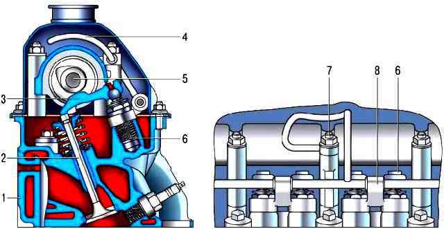
The valves move in the guide bushings under the action of the camshaft cams through the steel levers 3, resting with one shoulder on the spherical heads of the hydraulic bearings 6, the other on the ends of the valve stems 2.
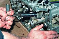
Hydro bearings are screwed into the sockets of the head of block 1.
Oil under pressure is supplied to the hydraulic bearings through a separate tube 4 ramps from the hole in the camshaft bearing housing near the middle pin of its fastening.
Since there are practically no gaps in the valve mechanism, the pressure springs of the levers used in the VAZ-21213 engine are excluded.
Pistons 10 are cast from aluminum alloy and coated with a layer of tin for improved running-in.
Piston skirts have a complex geometric shape: conical in height, with a large base at the bottom of the skirt, and oval in cross section, with a larger axis located perpendicular to the axis of the piston pin.
The axes of the holes for the piston pins are offset from the axis of symmetry of the pistons by 1.2 mm to the right side of the engine.
Two compression rings and one oil scraper are installed in the grooves of the pistons.
The groove of the oil scraper ring has through holes through which the oil collected by the ring is fed into the piston to lubricate the piston pin.
With 23 forged steel connecting rods, the pistons are connected by tubular section case hardened steel piston pins.
Floating type piston pins rotate freely in the upper connecting rod bosses and piston bosses.
The piston pins are fixed against axial movement by spring rings located in the grooves of the piston bosses.
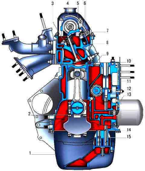
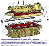
Camshaft 15 cast iron, cast, with bleached rubbing surfaces of the cams, mounted in a removable aluminum housing, mounted on the upper plane of the cylinder head 8, cast from an aluminum alloy.
It is driven from the crankshaft by a single-row roller chain 7.
The same chain drives the oil pump drive shaft.
The number of teeth of the oil pump drive shaft sprocket has been reduced from 38 to 30 compared to the VAZ-21213 engine in order to increase the oil pump feed.
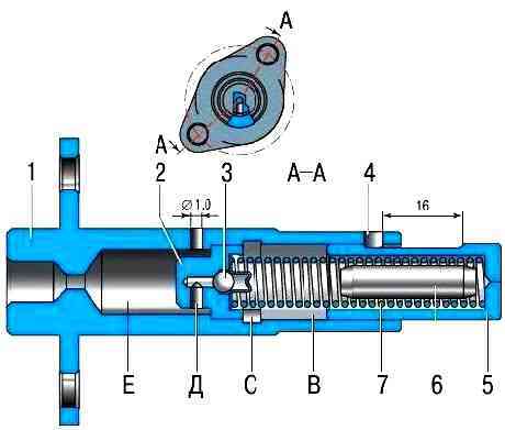
The chain in tension is maintained by a spring-hydraulic tensioner through a plastic shoe, the dimensions of which are significantly increased compared to the shoe of the VAZ-21213 engine, before starting the engine, the pre-tensioning of the chain is provided by spring 7, and after starting, by the pressure of the oil supplied through the steel tube from the adapter under the emergency oil pressure drop sensor.
Oil from the lubrication system through the tube 4 under pressure enters the cavity (E) of the tensioner, then through the hole (D) and valve assembly 2 enters the cavity (B), where it acts on the plunger 5.
In the body 1 of the tensioner, a drainage hole with a diameter of 1 mm is made to release air from the cavity (E).
The vibrations of the chain are damped by the damper, as well as the tensioner shoe, made of wear-resistant plastic.
A disposable gasket made of non-shrinking material is installed between the head and the block.
At the top, the head of the block is closed with a stamped steel cover 14, under which a sealing gasket made of a rubber-cork mixture is installed.
An oil sump 1 is attached to the lower part of the cylinder block through a rubber cork gasket, covering the cavity of the block from below and acting as an oil reservoir.
Lubrication system combined: under pressure and spray.
Main and connecting rod bearings, camshaft drive bearings and oil pump drive shaft, camshaft lobes and oil pump drive gear bushings are pressure lubricated.
Oil flowing from the gaps and splashed by moving parts lubricates the cylinder walls, pistons with piston rings, piston pins, the timing chain, the ball heads of the valve actuator hydraulic bearings, as well as the valve stems and their guide bushings.
The system consists of an oil sump 1 of a gear oil pump 15 with a built-in pressure reducing valve and an oil receiver with a coarse oil strainer, a full-flow fine oil filter 13 with bypass and anti-drain valves, a low oil pressure warning lamp sensor and oil channels.
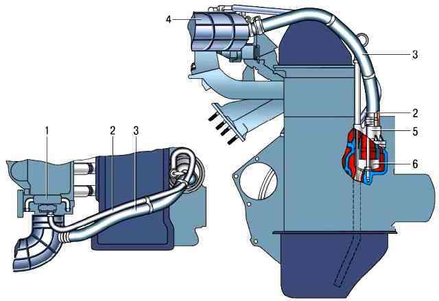
The ventilation system of the crankcase is closed, with the removal of crankcase gases through the oil separator 6 into the intake pipe, then the crankcase gases are sent to the engine cylinders, where they are burned.
When the engine is idling, crankcase gases enter through hose 2 of the primary circuit through the gauge this hole (jet) in the throttle body.
In this mode, a high vacuum is created in the intake pipe and crankcase gases are effectively sucked into the throttle space.
The jet limits the amount of exhaust gases so that the engine does not interfere with idling.
When the engine is running under load, when the throttle is partially or fully open, the main volume of gases passes through the hose 3 of the second circuit into the air inlet 4 in front of the throttle assembly and then into the intake pipe and combustion chambers.
Cooling system of the engine consists of a cooling jacket, made in casting and surrounding the cylinders in the block, combustion chambers and gas passages in the cylinder head and intake pipe.
Forced fluid circulation in the system is provided by a centrifugal water pump driven by a crankshaft using a V-belt, which simultaneously serves as a generator drive.
To maintain the normal operating temperature of the coolant, a thermostat is installed in the cooling system, which blocks a large circle of the system when the engine is cold and the coolant temperature is low.
The power supply system of the engine consists of an electric fuel pump installed in the fuel tank, a throttle assembly, a fine fuel filter, a fuel pressure regulator, injectors and fuel hoses.
The ignition system consists of an ignition module mounted on a special bracket on the cylinder block, spark plugs and high voltage wires.
The electronic engine control unit (ECU) controls the ignition system.


