")
")
")
")
")
")
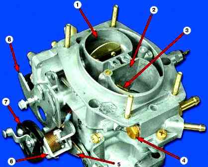
Solex type carburetor - emulsion type, two-chamber, with sequential throttle opening
Mechanical damper drive
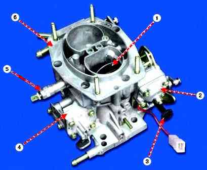
The carburetor has a balanced float chamber, a crankcase exhaust system, a heating of the first chamber throttle zone, a manual starter, an idle air shut-off solenoid valve.
Fuel is supplied to the carburetor through a strainer and a needle valve that maintains a predetermined fuel level in the float chamber.
The only difference is that the carburetor 21083–1107010-31 has a semi-automatic starting device.
And on the carburetor 2108,21081,21083 there is a mechanical one, which is controlled by the "suction" button.
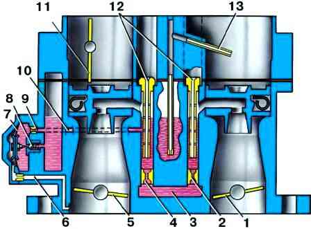
Main dosing system
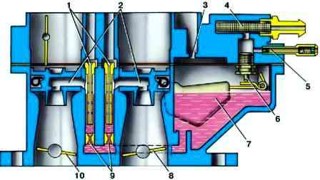
Fuel is fed through the strainer 4 (Fig. 1) and the needle valve 6 into the float chamber.
From the float chamber, the fuel enters through the main fuel jets 9 into the emulsion wells and mixes with the air leaving the holes of the emulsion tubes 1, which are made integral with the main air jets.
Through sprayers 2, the fuel-air emulsion enters the small and large diffusers of the carburetor.
Throttle valves 8 and 10 are interconnected in such a way that the second chamber starts to open when the first one is already open by 2/3 of the amount.
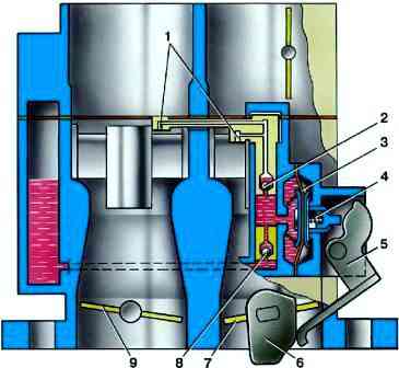
Idling system
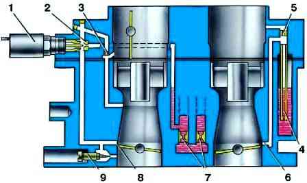
Fig. 2. Scheme of the idle system and transitional systems: 1 - electromagnetic shut-off valve; 2 - idle fuel jet; 3 - idle air jet; 4 - fuel jet of the transition system of the second chamber; 5 - air jet of the transition system of the second chamber; 6 - outlet of the transition system of the second chamber; 7 - main fuel jets; 8 - slot of the transition system of the first chamber; 9 - adjusting screw for the quality (composition) of the mixture
Takes fuel from the emulsion well after the main fuel jet 7 (Fig. 2).
Fuel is supplied to the fuel jet 2 with an electromagnetic shut-off valve 1, at the outlet of the jet it mixes with air coming from the flow channel and from the expanding part of the diffuser (to ensure the normal operation of the carburetor when switching to idle mode).
The emulsion exits under the throttle valve through a hole regulated by screw 9 for the content of carbon monoxide (CO) in the exhaust gases.
Transition systems
When the carburetor throttles are opened before the main metering systems are turned on, the air-fuel mixture flows:
- - into the first mixing chamber through the idle jet 2 and the vertical slot 8 of the transition system, located at the level of the throttle valve edge in the closed position;
- - into the second mixing chamber through the outlet 6, located just above the edge of the throttle valve in the closed position.
Fuel comes from jet 4 through a tube, mixes with air from jet 5 coming through the flow channel.
Power modes economizer
1 - throttle valve of the second chamber; 2 - main fuel jet of the second chamber; 3 - econostat fuel jet with a tube; 4 - main fuel jet of the first chamber; 5 - throttle valve of the first chamber; 6 vacuum transmission channel; 7 - economizer diaphragm; 8 - ball valve; 9 - economizer fuel jet; 10 - fuel channel; 11 - air damper; 12 - main air jets; 13 - econostat injection tube
It works at a certain vacuum behind the throttle valve 5 (Fig. 3).
Fuel is taken from the float chamber through ball valve 8.
The valve is closed as long as the diaphragm is held by vacuum in the intake pipe.
With a significant opening of the throttle valve, the vacuum drops somewhat and the diaphragm spring 7 opens the valve.
The fuel passing through the economizer jet 9 is added to the fuel that passes through the main fuel jet 4, enriching the combustible mixture.
Econostat
Operates at full engine load at speeds close to maximum, with wide open throttles.
Fuel from the float chamber through the jet 3 enters the fuel pipe and is sucked out through the injection pipe 13 into the second mixing chamber, enriching the combustible mixture.
Accelerator pump
1 - atomizers; 2 - ball fuel supply valve; 3 - pump diaphragm; 4 - pusher; 5 - drive lever; 6 - pump drive cam; 7 - throttle valve of the first chamber; 8 - check ball valve; 9 - throttle valve of the second chamber
Diaphragm, mechanically driven by cam 6 (Fig. 4) on the axis of the throttle valve of the first chamber.
When the throttle is closed, the spring pulls the diaphragm 3 back, which leads to filling the pump cavity with fuel through the ball valve 8.
When the throttle is opened, the cam acts on lever 5, and diaphragm 3 pumps fuel through ball valve 2 and nozzles 1 into the mixing chambers of the carburetor, enriching the combustible mixture.
The performance of the pump is not adjustable and depends only on the profile of the cam.
Semi-automatic launcher
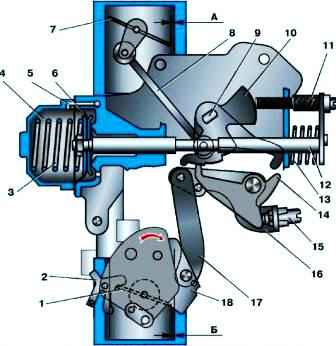
Improves vehicle control and reduces exhaust gas toxicity during engine start and warm-up (Fig. 5).
When starting a cold engine, the bimetallic spring of the starting device (not shown in Fig. 5) with the help of levers and rod 8 keeps the air damper 7 closed.
After starting the engine, the damper with the help of diaphragm 6 opens slightly to clearance A, which is adjusted by screw 11 of the stem 12 of diaphragm 6 of the starting device.
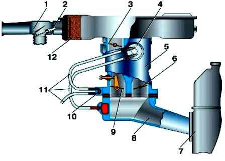
1 - thermostat; 2 - thermal power element of the thermostat; 3 - air damper; 4 - liquid chamber; 5 - carburetor; 6 - throttle valve of the second chamber; 7 - engine; 8 - inlet pipe; 9 - throttle valve of the first chamber; 10 - carburetor heating block; 11 - coolant hoses; 12 - air filter
As the engine warms up, the coolant circulating through the liquid chamber 4 (Fig. 6) of the starting device heats up and a bimetallic spring, which ensures the opening of the air damper through the levers of the drive of the starting device and the thrust 8 (see Fig. 5).
When the engine is warm, the air damper is fully open with a bimetallic spring.
Forced idle economizer
Disables the idle system during forced idle (during engine braking, downhill driving, gear shifting), reducing fuel consumption and hydrocarbon emissions.
In the forced idle mode, at a crankshaft speed of more than 2100 min -1 and with the carburetor limit switch closed to ground (pedal released), the shut-off solenoid valve turns off, the fuel supply is interrupted. p>
When the speed of the crankshaft at forced idle speed drops to 1900 min-1, the control unit turns on the electromagnetic shut-off valve (although the limit switch is turned on to ground), fuel begins to flow through the idle jet , the engine gradually idles.
Calibration data for carburetor 2108
Parameters of the first carburetor chamber
- Mixing chamber diameter, mm 32;
- Diffuser diameter, mm 21;
Main dosing system:
- fuel jet marking - 97.5;
- Air jet marking - 165
Emulsion tube type - 23
Idle system and transition systems:
- marking of the fuel jet - 42;
- Air jet marking - 170
Power Saver:
- fuel jet marking - 40;
- spring compression force at a height of 9.5 mm, N = 1.5±10%
Accelerator pump - 35;
- Atomizer marking - 7
- cam marking fuel supply for 10 cycles cm 3 - 11.5
Starting clearances:
- air damper, mm - 3±0.2;
- throttle valve, mm - 0.85
The diameter of the hole for the vacuum corrector is 1.2 mm
Needle valve hole diameter - 1.8 mm
The diameter of the fuel bypass hole in the tank is 0.7 mm
Diameter of the crankcase ventilation hole - 1.5 mm
Parameters of the second carburetor chamber:
- Mixing chamber diameter, mm 32;
- Diffuser diameter, mm 23;
Main dosing system:
- fuel jet marking - 97.5;
- Air jet marking - 125
Emulsion tube type - ZC
Idle system and transition systems:
- marking of the fuel jet - 50;
- Air jet marking - 120
Accelerator pump - 40;
- Atomizer marking -
- cam markings fuel supply for 10 cycles cm 3 - 11.5
Needle valve hole diameter - 1.8 mm
The diameter of the fuel bypass hole in the tank is 0.7 mm