To prevent breakage of the contact disc under the steering wheel, the following instructions should be observed:
- - before disconnecting the steering shaft from the steering mechanism, be sure to lock the steering wheel and wheels with a special device in the straight ahead position, and they must remain locked during the entire time of work;
- - If the alignment of the contact plate was not done correctly, you need to remove the steering wheel for re-centering.
Only experienced workers who have undergone special training are allowed to perform this operation.
Put the car on a two-post lift.
Remove the battery cover.
Disconnect the wires from the battery terminals, starting with the negative terminal.
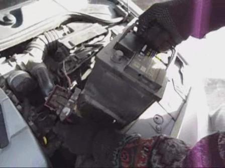
Remove the battery
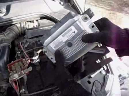
Remove the engine control
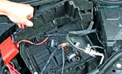
Remove the battery mounting shelf
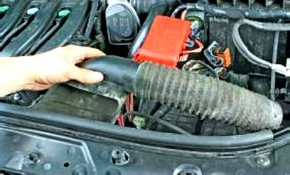
Remove the intake sleeve
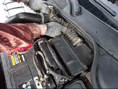
Loosen the clamps and remove the air supply sleeve from the air filter to the throttle assembly
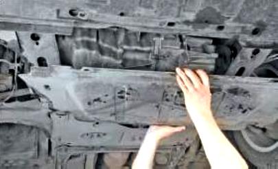
Remove the crankcase protection and engine mudguard
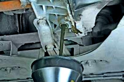
Draining the gearbox oil
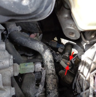
We press the lock of the tip of the gear selection cable
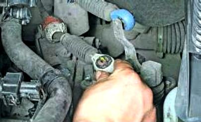
Disconnect the end of the cable from the gear selector on the gearbox.
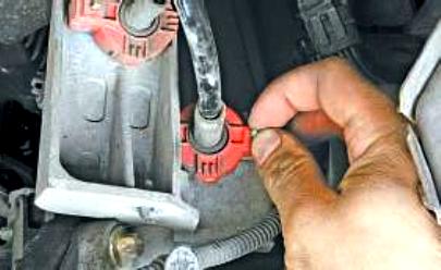
Also disconnect the tip of the shift cable
Retrieving the fixer
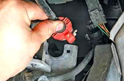
Remove the gear selection cable from the bracket.
We also remove the gearshift cable from the bracket
Unscrew the bolt securing the ground wire to the gearbox
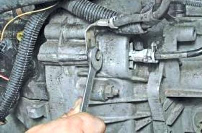
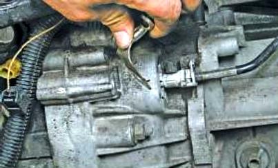
Set aside the mass wire
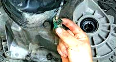
Pry off the retainer of the wiring harness of the reverse light switch
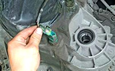
Disconnect the block from the switch
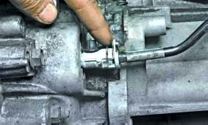
Press the clutch tube retainer
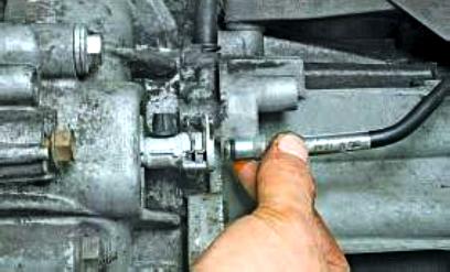
And disconnect the tube from the clutch slave cylinder.
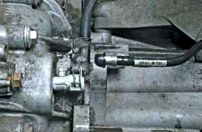
Remove the protective cap from the clutch hydraulic bleeder and plug the tube with it so that dirt does not get there
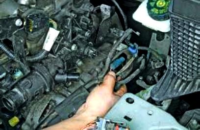
Remove the motor harness from the holder on the box and take it aside
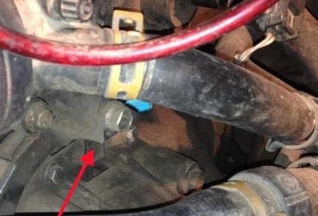
Disconnect the wiring harness block from the crankshaft sensor
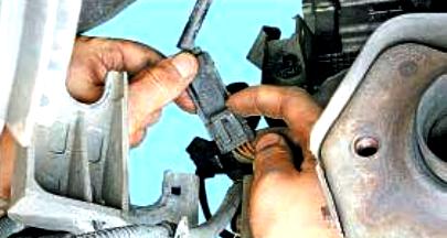
We press the clamp of the oxygen sensor harness block
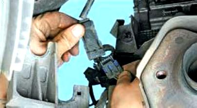
Disconnect the block from the harness
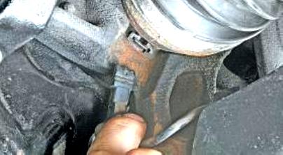
Disconnect the wiring harness block from the wheel speed sensor
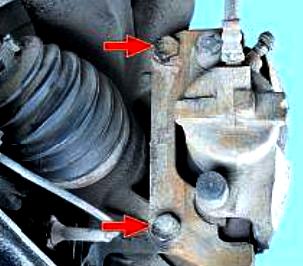
Remove the front wheels of the car and turn out two bolts securing the brake mechanisms to the steering knuckles
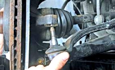
We take aside the caliper and fasten it with wire or hooks to the front suspension springs.
Disconnect the tie rods from the steering knuckle levers.
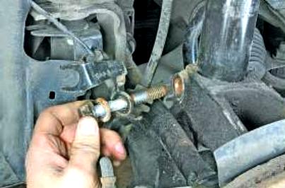
We unscrew the nuts of the shock strut bolts (one on each side) to the steering knuckles and remove the bolts from the holes of the strut knuckles.
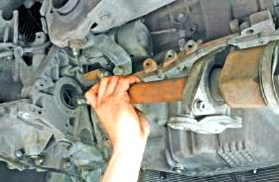
We set aside the steering knuckles and disconnect the internal hinges of the front wheel drives from the gearbox.
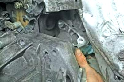
Remove the starter
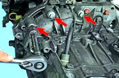
We unscrew the three upper bolts securing the gearbox to the engine
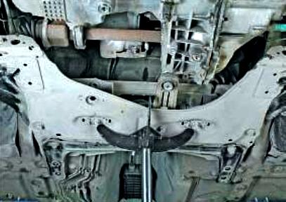
Remove the stretcher.
In the process of removing the subframe from the gearbox, disconnect the rear support alongtwo power unit
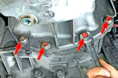
We unscrew the four bolts securing the engine oil sump to the clutch housing
We install reliable supports for the engine and gearbox.
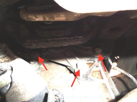
We unscrew the three bolts securing the gearbox housing to the left power plant suspension support (Fig. 32)
We shift the gearbox back until the clutch housing studs come out of the holes in the cylinder block.
In this case, the input shaft of the gearbox should come out of the hub of the clutch disc
We move the box as far back as possible, remove the support from under it and, tilting the back of the box down, remove it from the car.
When removing the box, try not to rest the input shaft of the box on the petals of the basket so as not to deform them.
Install
Do not apply grease to the input shaft of the gearbox, so as not to damage the clutch slave cylinder and the splines of the input shaft of the gearbox.
To prevent fluid leakage, be sure to replace the clutch slave cylinder when replacing the clutch cover.
Make sure that the mounting sleeves are present and correctly positioned to ensure alignment of the engine and gearbox relative to each other.
Installation is performed in the reverse order of removal.
When installing, be sure to tighten the bolt of the steering shaft universal joint yoke terminal connection.
Torque tighten:
- - wheel bolts (110 Nm);
- - hub nut (280 Nm);
- - nut of fastening of a pin of a spherical support of the suspension arm (62 Nm);
- - the nut of the ball joint pin of the tie rod end (37 Nm);
- - anti-roll bar ball joint pin nut (44 Nm);
- - side panel mounting bolts (2 Nm);
- - bolts for securing the gearbox and starter to the engine (44 Nm);
- - bolts for fastening the jet thrust to the engine (180 Nm);
- - bolts for fastening the jet thrust to the subframe (105 Nm);
- - bolts for fastening the pendulum support of the box (62 Nm);
- - nut for attaching the pendulum support to the cushion (180 Nm);
- - bolts for the terminal connection of the fork and the universal joint of the steering shaft (21 Nm);
- - front bolts for fastening the radiator cross member (105 Nm);
- - rear bolts for fastening the radiator cross member (210 Nm);
- - subframe cross member mounting bolts (62 Nm);
- - rear subframe mounting bolts (140 Nm);
- - bolts for fastening the connecting rods to the subframe (105 Nm);
- - gearbox drain plug (25 Nm);
- - gearbox filler plug (3 Nm).
Fill the gearbox with oil.
Be sure to bleed the clutch hydraulics as follows:
- - add brake fluid to the reservoir:
- - pump the hydraulic clutch:
- - add brake fluid to normal level.
Connect the wires to the battery terminals, starting with the positive terminal.


